
SLIDE 1
Agenda High Power MW and LW The NX Series Complete system packages - - PowerPoint PPT Presentation
Agenda High Power MW and LW The NX Series Complete system packages Some examples Chuck Kelly Director of Sales MDCL makes $ence! AUI functionality Nautel Commissioning, Training and Support Wendell Lonergan Your
Chuck Kelly Director of Sales Wendell Lonergan Head of Sales
Enter questions here …then press Send
Click on to
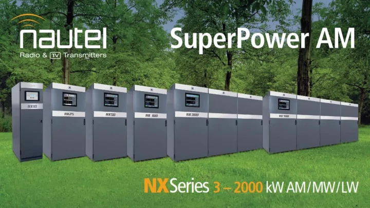
NX50 NX25
Combined Solutions up to 2 MW
NX100 NX200 NX300 NX400 NX15/25 NX3/5/10
38” (0.96m) 44” (1.12m) 72.5” (1.84m)
“The NX Series of AM transmitters are the first high power AM transmitters to be provided with Dynamic Pre-correction”
2.5kW 2.5kW 2.5kW 2.5kW
. . . .
2.5kW 2.5kW
160 Modulator / RF Amps
Series Combiner Dual T Output Matching Network
Main/Alt Supervision / Control
RF Drive DSP Exciter DSP Exciter Audio Inputs: AES/EBU, Analog L&R, I&Q Optional GPS Manual Control 15” LCD GUI TCP/IP Webserver / Remote Control RF Driver PS RF Driver PS Fan PS Fan PS Controller PS Controller PS 400V DC
Mod Drive 1-3 Mod Drive 4-6 Mod Drive 7-9
Mains Transformer Phase Control Rectifier Choke Input Filter
+ RF
L&R, and I&Q inputs.
ultimate frequency accuracy.
12 kW continuous power rating
(NX module operated at 2.5 kW of carrier)
200 A FET’s: Replaceable with just a screwdriver Hall Effect Current Sensor Drive Transformers RF Driver Modulator Replaceable Fuse Modulator Input RJ45 RF Amplifier
PA Efficiency
Q1 Q2 Q3 Q4 Q5 Q6 Q7 400 VDC Output+ Output-
Modulator Stage RF Amplifier Stage RF FET (x4) Modulator FET (x3) B+ Supply SiC Rectifiers (x3) Modulator Filter Digitally Controlled RF Drivers (x4) Digitally Controlled Modulator Drivers (x3)
copper pipes with ferrite cores which couple the RF output.
required power.
NX (the other is the fans)
frequency dependent section in the NX Series.
shunt 3rd harmonic trap.
provides minimal amplitude and phase distortion to the RF signal.
band may be accomplished in just a few hours.
for all MW frequencies is available.
PA_1 PA_2 PA_n Output
Adjustable Carbon Ball Gap Calibrated Fast Spark Gap (Pressurized Tritium) Series Resonant High Pass Section Voltage and Current Measurement for Active Protection Forward and Reflected Directional Coupler Ports for Spectrum Verification Combiner Transformers Harmonic Filter RF Amplifiers Frequency Agile: Harmonic Filter Re-Tune in a Few Hours
Tritium)
Transformer Secondary (Common Mode)
B+ Rectifiers (Differential Mode)
1.75 MV to LV Transformer 6600 VAC to 310 VAC Single step conversion increases system efficiency LV AC feed to Transmitter High Current Cabling System 310 VAC 3Φ 2700 Amps per line 24 conductors in 8 groups 3 conductors to each 100 kW block
each containing two ball bearing fans.
working.
monitored by the controller.
as a typical 10 kW FM transmitter.
a washable metal air filter.
configurations are fed through a large, high efficiency transformer in a separate
transmitter.
controlled three phase rectifier bank which provides voltage control and soft start.
en large fuses protect banks of 4 modules.
with a large bank of electrolytic capacitors.
completely redundant.
performance limits.
RMS power from a given power transmitter with better MER.
performance.
The Nautel NX series leads the industry in Digital Radio development
The Nautel NX is the world leader in high efficiency AM transmission
– 90% for NX 100 kW and higher – 88% for 50 kW and below
– Modulation Dependant Carrier Level (MDCL) standard – all popular algorithms are included – up to an additional 30% savings in electrical costs – no discernable coverage or performance reduction.
“With reduced electrical costs the purchase price of an NX can often be paid off in just a few years when compared to older tube and solid state designs.”
No information yet contains >2/3 of the transmitted power.
Modify transmitted waveform to reduce power without reducing received quality in receivers
DAM, Full DAM, DCC, AMC
– Average power consumption is approximately 666 kW @ 100% mod. – 8760 hours per year (24 hr station) – 5.83 MWhr per year – Electrical rates can range from 5 - 20 cents depending on the region Assuming a 30% power reduction: – Savings are $175,000 per year at a 10 cent/kWhr rate – Savings are $262,000 per year at a 15 cent/kWhr rate If replacing an older 70% efficient transmitter: – Savings are $291,000 per year at a 10 cent/kWhr rate – Savings are $437,000 per year at a 15 cent/kWhr rate
NX Advanced User Interface includes extensive instrumentation features:
and average levels
average
envelope
chart
levels at all levels including the power modules
Spectrum Analyzer: Displays the spectrum of the transmitted signal. EQ Frequency Response: Shows the frequency response of the modulator’s EQ filter. EQ Impulse Response: Shows the impulse response of the modulator’s EQ filter. EQ Filter Delay: Shows the delay of the modulator EQ across its bandwidth. AM-AM Correction: Shows the amplitude compensation applied to the magnitude. AM-PM Correction: Shows the phase compensation applied to the RF drive signal. Signal Constellation: Shows the phase and amplitude of the symbols being modulated within an OFDM sub- carrier as dots on a cartesian graph. Lissajous Plot: Displays the level and phase of L&R input audio. Smith Chart: Displays the impedance of the load as seen at the combiner. Modulation Levels: Displays L+R modulation, PDM and I/Q modulation. Audio Inputs: Displays the program input levels. Bar graph labels indicate the source of each display.
– Power – Operating mode (Analog / DRM / Simulcast) – Audio input selected / audio input level
day / week basis.
Separate power processing stages for Envelope Modulation and RF Amplification are employed. This approach enjoys the following benefits:
convert DC to RF and vary the RF envelope.
switching loss across the AM band
conduction loss
VSWR
further improve robustness
1 2 3 4 5 6 x 10
0.5 1 Modulation Process 1 2 3 4 5 6 x 10
0.5 1 1 Phase Modulator 1 2 3 4 5 6 x 10
0.5 1 9 Phase Modulation
1600 kW
1200 kW 2000 kW
NX400 NX400 1.75 MVA Transformer MV Primary 310 VAC Secondary Cable Trays MV Primary Switch (Optional) LV (310 V) Switch for 800kW LV (310 V) Qty (8) 500 A CB for cable fault protection
1.5 MW LW
(4) NX-400 (4) Mains Transformers Four port 1.5 MW Combiner
NX50 NX25 NX100 NX200 NX300 NX400 NX15/25 NX3/5/10 Combined to 2 MW
– Bangor, Halifax
– Bangor, Halifax, Memphis – Memphis quick-ship depot
– Support for every Nautel product ever made, no matter when it was manufactured.
Enter questions here …then press Send
Click on to
http://www.nautel.com/newsletter/
http://www.nautel.com/webinars/
http://www.youtube.com/user/NautelLtd
sales@nautel.com www.nautel.com
Director of Sales Chuck.Kelly@Nautel.com