
SLIDE 1
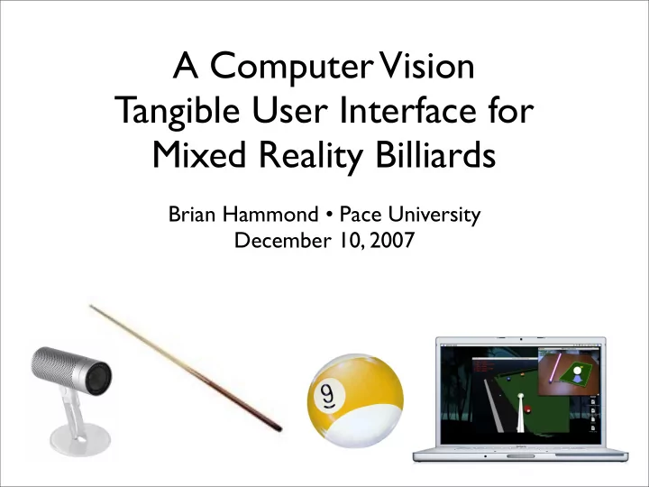
A Computer Vision Tangible User Interface for Mixed Reality Billiards
Brian Hammond • Pace University December 10, 2007
A Computer Vision Tangible User Interface for Mixed Reality - - PowerPoint PPT Presentation
A Computer Vision Tangible User Interface for Mixed Reality Billiards Brian Hammond Pace University December 10, 2007 Introduction HCI is study of how humans interact with computers The mouse and keyboard limits richness of
Brian Hammond • Pace University December 10, 2007
TUI CV-based input
MR-based Billiards
Client-server using TCP/IP for IPC
Feature Helps find.. Detection is.. Description cloth cue stick, ball, shadow automatic container Tr h manual
top point of ref object
Br h manual
bottom point of ref object
St h manual shadow of Tr cue tip distw automatic tip of cue stick shaft θ, ψ automatic cue stick shaft shadow θ automatic shadow of shaft Sc shadow automatic shadow of tip of stick planar object h automatic
edges used to find parallel lines
parallel lines h automatic
find vanishing line of plane of desk
diagram adapted from Reid paper for our TUI setup
diagram adapted from Reid paper for our TUI setup
Line Description l1
through reference object shadow (Tr-Br)
l2
through Sc parallel to l1; hence l2 intersects l1 on vanishing line
l3
through Tr and Sc
l4
through cue tip and Tr
l5
through Br and intersection of l3 and l4; intersection of l5 and l1 is projection of cue tip on plane (Pb)
l6
through Tr and intersection of l5 and vanishing line
l7
through cue tip and intersection of l5 and vanishing line
l8
through Tr and Br
l9
through Pb and cue tip
M and Ms are arbitrary points along the cue stick shaft and its shadow, respectively.
(practice strokes) (shooting) (most recent local max)
(hit ball)
Library (wonderful!), CiteCeer, Google Scholar, and CiteULike.
(active markers), template matching, Hough transforms for finding edges of cue stick, full 3D reconstruction using camera calibration, etc.
(3D rendering), Google SketchUp (content creation), Ruby (export script), Scons (server builds), Apple XCode (client builds)
OmniGroup’s OmniGraffle