
9
Data Link Layer
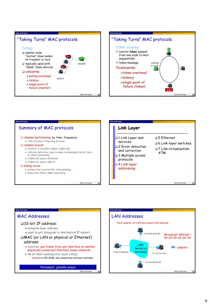
“Taking Turns” MAC protocols
Polling:
master node
“invites” slave nodes to transmit in turn
typically used with
“dumb” slave devices concerns:
polling overhead latency single point of
failure (master) master slaves
poll data data
Data Link Layer
49
Data Link Layer
“Taking Turns” MAC protocols
Token passing:
control token passed
from one node to next sequentially.
token message
concerns:
token overhead latency single point of
failure (token)
T data
(nothing to send)
T
Data Link Layer
50
Data Link Layer
Summary of MAC protocols
channel partitioning, by time, frequency
Time Division, Frequency Division
random access
ALOHA, S-ALOHA, CSMA, CSMA/CD Collision detection: easy in some technologies (wire), hard
in others (wireless)
CSMA/CD used in Ethernet CSMA/CA used in 802.11
taking turns
polling from central site, token passing Bluetooth, FDDI, IBM Token Ring Data Link Layer
51
Data Link Layer
Link Layer
1 Link Layer and
services
2 Error detection
and correction
3 Multiple access
protocols
4 Link-layer
addressing
5 Ethernet 6 Link-layer switches 7 Link virtualization:
ATM
Data Link Layer
52
Data Link Layer
MAC Addresses
32-bit IP address:
network-layer address used to get datagram to destination IP subnet
MAC (or LAN or physical or Ethernet)
address:
function: get frame from one interface to another
physically-connected interface (same network)
48 bit MAC address (for most LANs)
- burned in NIC ROM, also sometimes software settable
Permanent, globally unique
Data Link Layer
53
Data Link Layer
LAN Addresses
Each adapter on LAN has unique LAN address
Broadcast address = FF-FF-FF-FF-FF-FF = adapter
1A-2F-BB-76-09-AD 58-23-D7-FA-20-B0 0C-C4-11-6F-E3-98 71-65-F7-2B-08-53
LAN (wired or wireless)
Data Link Layer
54