2020
play

2020 July 9-10, Design of an Experimental Apparatus to Test the - PDF document

Transactions of the Korean Nuclear Society Virtual Spring Meeting 2020 July 9-10, Design of an Experimental Apparatus to Test the Alkali-Metal Heat Pipes for Space Fission Power Sung Deok Hong * and Chan Soo Kim Korea Atomic Energy Research


  1. Transactions of the Korean Nuclear Society Virtual Spring Meeting 2020 July 9-10, Design of an Experimental Apparatus to Test the Alkali-Metal Heat Pipes for Space Fission Power Sung Deok Hong * and Chan Soo Kim Korea Atomic Energy Research Institute, 111, Daedeok-daero 989 Beon-gil, Yuseong-gu, Daejeon 34057, Korea * Corresponding author: sdhong1@kaeri.re.kr 1. Introduction 
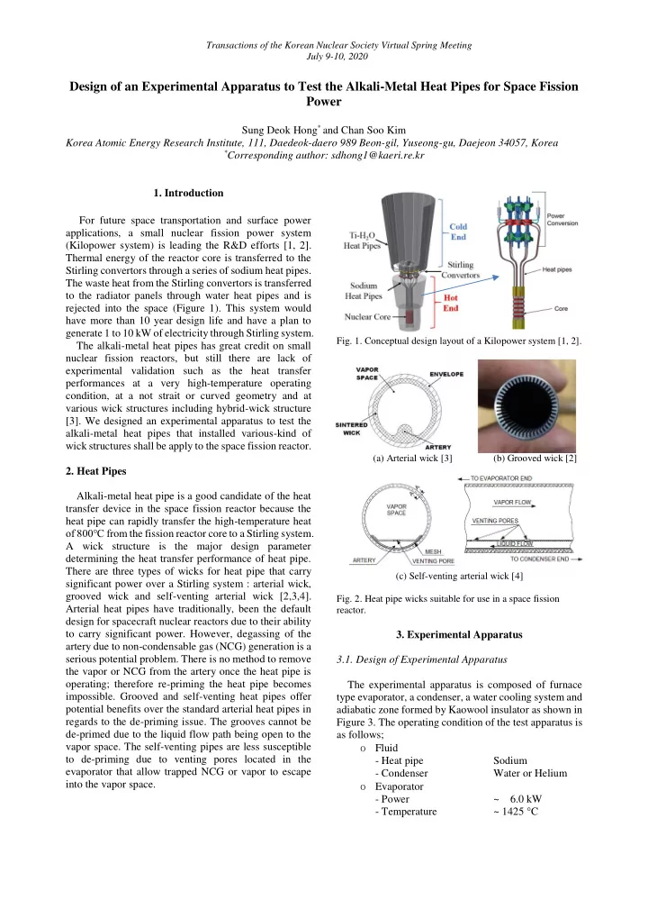
For future space transportation and surface power applications, a small nuclear fission power system (Kilopower system) is leading the R&D efforts [1, 2]. Thermal energy of the reactor core is transferred to the Stirling convertors through a series of sodium heat pipes. The waste heat from the Stirling convertors is transferred to the radiator panels through water heat pipes and is rejected into the space (Figure 1). This system would have more than 10 year design life and have a plan to generate 1 to 10 kW of electricity through Stirling system. Fig. 1. Conceptual design layout of a Kilopower system [1, 2]. The alkali-metal heat pipes has great credit on small nuclear fission reactors, but still there are lack of experimental validation such as the heat transfer performances at a very high-temperature operating condition, at a not strait or curved geometry and at various wick structures including hybrid-wick structure [3]. We designed an experimental apparatus to test the alkali-metal heat pipes that installed various-kind of wick structures shall be apply to the space fission reactor. (a) Arterial wick [3] (b) Grooved wick [2] 2. Heat Pipes Alkali-metal heat pipe is a good candidate of the heat transfer device in the space fission reactor because the heat pipe can rapidly transfer the high-temperature heat of 800℃ f rom the fission reactor core to a Stirling system. A wick structure is the major design parameter determining the heat transfer performance of heat pipe. There are three types of wicks for heat pipe that carry (c) Self-venting arterial wick [4] significant power over a Stirling system : arterial wick, grooved wick and self-venting arterial wick [2,3,4]. Fig. 2. Heat pipe wicks suitable for use in a space fission Arterial heat pipes have traditionally, been the default reactor. design for spacecraft nuclear reactors due to their ability to carry significant power. However, degassing of the 3. Experimental Apparatus artery due to non-condensable gas (NCG) generation is a serious potential problem. There is no method to remove 3.1. Design of Experimental Apparatus the vapor or NCG from the artery once the heat pipe is operating; therefore re-priming the heat pipe becomes The experimental apparatus is composed of furnace impossible. Grooved and self-venting heat pipes offer type evaporator, a condenser, a water cooling system and potential benefits over the standard arterial heat pipes in adiabatic zone formed by Kaowool insulator as shown in regards to the de-priming issue. The grooves cannot be Figure 3. The operating condition of the test apparatus is de-primed due to the liquid flow path being open to the as follows; vapor space. The self-venting pipes are less susceptible ο Fluid to de-priming due to venting pores located in the - Heat pipe Sodium evaporator that allow trapped NCG or vapor to escape - Condenser Water or Helium into the vapor space. ο Evaporator - Power ~ 6.0 kW - Temperature ~ 1425 °C

  2. Transactions of the Korean Nuclear Society Virtual Spring Meeting July 9-10, 2020 ο Condenser capacity than gas. The condenser has heat pipe guides, thermocouple port, an assembling flange and a sealing - Pressure ~ 10.0 bar adapter (Figure 5). This condenser has total of 6kW heat - Temperature (water) < 200 °C rejection capacity when the temperature difference - Flowrate (water) ~ 0.05 kg/s between coolant inlet and outlet is 50°C with flowrate of 0.03 kg/s (Table I). The physical parameters that will be measured are the A problem is aroused in designing high-temperature electric power, temperature, heat loss, and coolant sealing of this condenser because the surface temperature flowrate. of alkali-metal heat pipe shall increase up to 750°C at normal operating condition. As an interim design stage, we invented a graphite-sealing adapter that will be withstand up to 450°C as shown in Figure 5. Later, we will replace the adapter as a Lava-sealing adapter that shall be withstand up to 870°C. Table I: Condenser thermal hydraulic data Parameter Unit Value Cooling capacity kW 6.0 (a) 3D layout of test section Pressure bar 1.0 City water Flowmeter Filter ℃ Condenser in/out temp. 20/70 Flow rate kg/s 0.029 Diameter (nozzle) mm 10.9 Coolant velocity (nozzle) m/s 0.31 Disposal PT TC Condenser (b) Coolant supply loop for condenser Fig. 3. Layout of experimental apparatus. 3.2. Evaporator Evaporator is a furnace type heater simulating reactor Fig. 5. Condenser. core thermal condition (Max. temperature to 1425°C). A Kanthal heater molded with Ceramic Kaowool material 3.4. Test Section can generate up to 6 kW thermal power. The heater is surrounded by thick Kaowool-insulator to minimize heat Sodium Heat Pipe (HP) has 3/4” diameter and 1.0 loss to the environment as shown in Figure 4. Two meter long tube geometry. The HP is filled with 50 grams variable AC autotransformers, Slidacs, will be connected of sodium that is the amount of emerging all the screen to the evaporator for control the power manually. wicks installed in the HP internal. Figure 6 shows the layout of test section installed in both evaporator and condenser. 25cm of HP is inserted into the evaporator and 20cm inserted condenser, and the other 55cm is opened at adiabatic region. K-type thermocouples are attached on the HP wall surface as shown the Figure 6. Stainless Steel bands fix the thermocouples except the evaporator region. In the evaporator region, the thermocouples are attached to the HP wall surface manually through the holes prepared to thermocouples at the ceramic blocks (insulator) in the evaporator. Fig. 4. Evaporator. 3.3. Condenser A water-pool type condenser is designed. It is convenient to measure the maximum heat transfer rate of various heat pipes because water has higher heat removal Fig. 6. Test section layout and thermocouple points

  3. Transactions of the Korean Nuclear Society Virtual Spring Meeting July 9-10, 2020 performance of a heat pipe in which have various kind of wicks as acquired in a commission test result. High 4. Commissioning Results temperature sealing adapter allows direct immersion of Some interesting facts are aquatinted on the heat pipe to coolant that makes accurate measurement of commissioning test. First, the sodium melts slowly if not heat transfer rate. Our condenser has advanced function insulated at the adiabatic region. When we wrap a than jacket type condenser, but it has a handicap that Kaowool insulator on the adiabatic region, the melting need to additional high temperature sealing adaptor. was done fast. One hour later after turn on the evaporator power, the surface temperatures at adiabatic region ACKNOWLEDGEMENTS increased subsequently by more then 400°C after the temperature rises in the order close to the temperature at This study was supported by the National Research the evaporator as shown in Figure 7. At the sealant Foundation of Korea (NRF) grant funded by the Korea location, we have to wait a long time until the sodium government (2019M2D1A1058139). melt. The reason is that the condenser filled with cold water. When the temperature at the sealant location REFERENCES reaches 330°C, a temperature fluctuation is started. As represented a small icon in the Figure 7, the amplitude of [1] M. A. Gibson, S. R. Oleson, D. I. Poston and P. McClure, temperature is from ± 10 to ± 15°C. The fluctuating "NASA's Kilopower Reactor Development and the Path to temperature initially decreases briefly and then increase Higher Power Missions," in IEEE Aerospace Conference, Big Sky, MT, 2017. again. This fluctuation tends to decrease as the [2] K. L. Walker, C. Tarau, and W. G. Anderson “Alkali Metal temperature rises. The temperature at the condenser Heat Pipes for Space Fission P ower,” Nuclear and Emerging region follows very slowly to the temperature of sealant Technologies for Space (NETS-2013), Albuquerque, NM, location. When a certain temperature is reached, the February 25-28, 2013 temperature at the condenser region 1 fluctuates with an [3 ] L. Mason and C. Carmichael, “A Small Fission Power amplitude that is several times larger than that of the System with Stirling Power Conversion for NASA Science sealant location. When water is supplied, the temperature Missions,” Nuclear and Emerging Technologies for Space dropped rapidly. (NETS-2011), Albuquerque, NM, February 7-10, 2011. Meanwhile, the maximum temperature of the [5] T. Kaya, Analysis of vapor – gas bubbles in a single artery evaporator is maintained so as not to exceed 1200°C. heat pipe, Int. J. Heat Mass Transfer 52 (2009) 5731 – 5739. Compared to the rate of temperature increase of the [4] K. L. Lee, C. Tarau and W. G. Anderson, Titanium Water maximum evaporator temperature, the temperature of the Heat Pipe Radiators for Space Fission System Thermal HP wall in evaporator continued to increase to 900°C. Management, Joint 19th IHPC and 13th IHPS, Pisa, Italy, June 10-14, 2018 Fig. 7. Commissioning results (evaporator Max. temperature 1case, heat pipe wall temperature 8 cases) 5. Conclusion . We designed an experimental apparatus to test the alkali-metal heat pipes that installed various-kind of wick structures shall be apply to the space fission reactor. Proper design and operation of condenser is an important work to figure out accurate measurement of heat transfer

Download Presentation
Download Policy: The content available on the website is offered to you 'AS IS' for your personal information and use only. It cannot be commercialized, licensed, or distributed on other websites without prior consent from the author. To download a presentation, simply click this link. If you encounter any difficulties during the download process, it's possible that the publisher has removed the file from their server.

Recommend


More recommend