1A89 Push-Open Undermount Slide (16mm) Specifications Length: - - PDF document

1a89
SMART_READER_LITE
LIVE PREVIEW

1A89 Push-Open Undermount Slide (16mm) Specifications Length: - - PDF document

Undermount Slides 1A89 Push-Open Undermount Slide (16mm) Specifications Length: 250mm to 600mm Travel: Full Extension Maximum Drawer Side Thickness: 16mm Max. Load Capacity: 45 kg(100 lb)/pair Mount: Undermount Material:


slide-1
SLIDE 1

1.16

Undermount Slides

King Slide reserves the right to alter specifjcations of all the products without notice. If the entity is different from the illustration, please refer to the entity.

  • Handle-free push-open allowing for complete drawer access

even when hands are full

  • Drawers can be ejected to its full extent even when at its full

weight bearing capacity

  • All mechanical device, instead of electric-driven, ergonomic

and energy saving

  • Undermount with full extension travel length
  • Ultra smooth with high rigidity and stability design
  • Signature patent pending tool-less ejection-force adjustment to

fit your convenience

  • Ergonomic design to increase usability and efficiency
  • 2 dimensional trimming system provides tool-less height and

depth adjustments

  • Effortless assembly and removal of drawer with front release

lever

  • High dynamic loading capacity of 34kg (75lb) with 100,000

life cycles, or 45kg (100lb) with 50,000 life cycles

  • High installation allowances for drawer width: +0.5/-1.5 mm,

and for drawer depth: +1/-1 mm
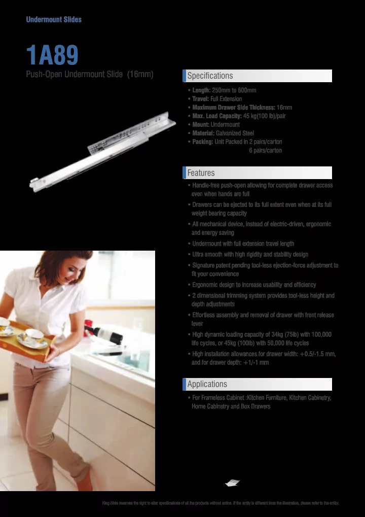
1A89

  • Length: 250mm to 600mm
  • Travel: Full Extension
  • Maximum Drawer Side Thickness: 16mm
  • Max. Load Capacity: 45 kg(100 lb)/pair
  • Mount: Undermount
  • Material: Galvanized Steel
  • Packing: Unit Packed in 2 pairs/carton

6 pairs/carton

Push-Open Undermount Slide (16mm)

Φ

Specifications Features Applications

  • For Frameless Cabinet :Kitchen Furniture, Kitchen Cabinetry,

Home Cabinetry and Box Drawers

slide-2
SLIDE 2

1.17

www.kingslide.com

King Slide reserves the right to alter specifjcations of all the products without notice. If the entity is different from the illustration, please refer to the entity.

Undermount Slides

1

32 32 32

18 18

9

4 37 96 192 288

250 300 350 400 450 500 550

(max)

X O

Φ

Drawer Removal: Simply press the front release device to remove the drawer

Φ

Drawer Release +3.5mm

R

  • l

l

Tool-less Height Adjustment : Simply rotate the wheel at the front bottom

  • f the drawer to adjust the drawer height

Dimension Specifications

Item No. Total Length (mm) Slide Travel (mm)

  • Max. Loading Capacity

kg(lb) / pair 1A89-250 250 224 45 (100) 1A89-300 300 280 45 (100) 1A89-350 350 340 45 (100) 1A89-400 400 390 45 (100) 1A89-450 450 440 45 (100) 1A89-500 500 490 45 (100) 1A89-550 550 540 45 (100) 1A89-600 600 590 45 (100) Cabinet Holes Position Easy Assembly with Front-End Installation Our specially designed front-end installation allows quick and simple drawer installation and removal processes. The quick connect and disconnect device is located at the front-end under the drawer, keeping intact the elegant appearance of the drawer.

  • Red Dots : Minimum Screw Required

Chipboard Screw System Screw

X

Round Heard Screw Space Requirement

Φ

W-42 W

+0.5
  • 1.5

min 6 max 16 37 21 min 27.5 max 13 W : Internal Cabinet Width

Note: Ensure the slide is parallel to the horizon or tilt to cabinet front on both sides during installation.

Note: Holes other than those shown may be in the slide member at King Slide's option and may change without notice.

slide-3
SLIDE 3

1.20

Undermount Slides

King Slide reserves the right to alter specifjcations of all the products without notice. If the entity is different from the illustration, please refer to the entity.

Overlay Drawer Front Inset Drawer Front

  • 1. Before installing the slides, make sure the dimensions of the cabinet and drawer meet the requirements specified in Fig. 1 and 2.
  • 2. Drill holes on the cabinet following the 'Cabinet Holes Position' drawing on the reverse page. Mount the slides on the cabinet using the

recommended type of screws.

  • 3. Make cut-outs on the drawer according to Fig. 3A and Fig. 3B's dimension (Using the drill template FL00ZD0-A as page 1.39 is recommended),

then install the front release lever according to Fig. 3A.

1A89 & 1B89

Front View Dimension Specification

W-42 W

+0.5
  • 1.0

min 6 max 16 37 21 min 27.5 max 13 W: Internal Cabinet Width W-49 W

+0.5
  • 1.0

min 6 max 19 37 24.5 min 27.5 max 13 W : Internal Cabinet Width

  • Fig. 1

Side View

  • Fig. 2

Installation Instruction

Inset Install Formula X 18 19 20 21 22 23 24 Y 59 60 61 62 63 64 65 Z 26 27 28 29 30 31 32 L: Slide Length X: Front Panel Thickness

Note: Ensure the slide is parallel to the horizon

  • r tilt to cabinet front on both sides

during installation.

  • Fig. 3A
  • Fig. 3B

Installation Requirement 1A89 1B89 You can use optional drill template FL-00ZD0-A as page 1.39

slide-4
SLIDE 4

1.21

www.kingslide.com

King Slide reserves the right to alter specifjcations of all the products without notice. If the entity is different from the illustration, please refer to the entity.

Undermount Slides

1

  • 4. Pull out the slides on the cabinet.
  • 5. Position and align the drawer with the slide as shown in Figs. 4A and 4B. Push the drawer all the way into the cabinet as shown in Fig. 4C until

clicked to complete the installation.

  • 6. After confirming the drawer is operating normally, install the front panel.
  • 7. If height / depth adjustment is needed after installation, please refer to the Detail Adjustment Info. below or the feature diagram on the previous

page.

Inward Outward Outward Inward

Eject Force Adjustment

Max. Min.

  • 1.0

4.0 +2.0

Factory setting

Front Gap Adjustment Detail Adjustment Info

  • Fig. 4A
  • Fig. 4B
  • Fig. 4C

To prevent installation errors which may lead to the drawer getting stuck, Please make sure the nomal operation of the drawer before securing the front panel.

Notes for installation

  • 1. Ensure the drawer body appearance is upright. It could not be diamond trapezoidal or distorted!
  • 2. Ensure the side space, depth on both sides are consistent.
  • 3. Ensure the installation location or the cabinet is on a flat surface.
  • 4. Ensure the front release lever is installed correctly.
  • 5. Ensure the drawer dimensions, rear notch locking hole, internal drawer width, and the drawer bottom recess are correct.

Notice