10 years of waveform analysis from 40 msa s to 40 gsa s
play

10 Years of waveform analysis from 40 MSa/s to 40 GSa/s Aug. 2018 - PowerPoint PPT Presentation

W orking W ith W aveforms Sebastian White, CERN/U.Virginia Sept. 12, 2018 ULTIMA 2018 Argonne National Lab HL-LHC upgrade program has renewed interest in Charged Particle timing* at << 100


  1. W orking W ith W aveforms 
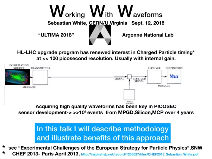
Sebastian White, CERN/U.Virginia Sept. 12, 2018 “ULTIMA 2018” Argonne National Lab HL-LHC upgrade program has renewed interest in Charged Particle timing* at << 100 picosecond resolution. Usually with internal gain. Acquiring high quality waveforms has been key in PICOSEC sensor development-> >>10 6 events from MPGD,Silicon,MCP over 4 years In this talk I will describe methodology and illustrate benefits of this approach * see “Experimental Challenges of the European Strategy for Particle Physics”,SNW * CHEF 2013- Paris April 2013, http://inspirehep.net/record/1256027/files/CHEF2013_Sebastian_White.pdf � 1

  2. 10 Years of waveform analysis from 40 MSa/s to 40 GSa/s Aug. 2018 PICOSEC Test Beam ~2010 ATLAS ZDC waveforms MCP* ref. time, HyperFastSilicon reconstructed from PPM samples -> sub- 100 picosec resolution SNW, Diffraction 2010 https://arxiv.org/abs/1101.2889 http://library.wolfram.com/infocenter/Articles/7716/ LRS ”Wavemaster” * MCP= MicroChannel PMT detecting Cerenkov from window � 2

  3. July/Aug 2017 PICOSEC data HyperFastSilicon(HFS) MMegas-based (mesh readout DD-AD) “PICOSEC” 4x 6micron HPK MCP ’s 64 mm 2 /pixel 80 mm 2 pixel +3mm Quartz (measure<20 picosec) (measure<25 picosec) (measure ~4 picosec) 10 pad “PICOSEC” Ne/C2H6/CF4 Si- Gallium doped vacuum RMS=19 picosec � 3

  4. 2 Fast Timing Projects based at CERN (we share resources, beam, ++) MPGD PICOSEC: RD51 common Fund proposal in 2014 by SNW and I. Giomataris new paper this week: Silicon HFSilicon: “Sensors with Internal Gain”-started in 2015 subset originated in 2011 DOE AD R&D award to: �4

  5. Growing, highly motivated group w. serious commitment to Instrumentation � 5

  6. Outline 1) Development of PICOSEC MPGD based detector (24 picosec) -Cerenkov Radiator, similarities to MCP -Drift Region-dominant role of diffusion and Gain 2) Application of similar modeling tools (SILVACO) for Silicon (20 picosec) -SILVACO tct-edge scan tool- with Ranjeet Dalal, Delhi -realistic Landau/Vavilov- thin samples- with Su Dong, Stanford 3) tools for FEE development -CIVIDEC development -w E.Griesmayer, Vienna -Transimpedance amp -w. M. Newcomer(+E.Morales), U. Penn -quad fast ASIC (SiGe)- “ “-(w. US/CMS support) 4) Strategies for digitization -CMS Barrel Timing Layer prototype data (LYSO/SiPM) -other applications � 6

  7. It Takes Time detection/multiplication in Silicon detectors(1972) in Gas detectors (1910) Theory and practice of Si w. internal gain relatively new. 1) most common,“reachthrough” diodes (aka “lgad”) ~1970’s, MIP timing in ’90’s 2) higher gain, “deep depleted” (our focus) started in ’90’s cooperative R&D w Gas(RD51) benefitted less mature Si modeling � 7

  8. ATLAS/CMS timing upgrades all based on Si w gain ->justifies continued development of underpinnings interesting, possibly deep, phenomena not yet traceable to particular gain model waveform data may reveal features not anticipated in models ->Si structure modification to mitigate degradation (~x2) due to Landau? -> “”” “ “ degradation due to radiation damage? …… this worked w. PICOSEC (see below)-> then traced to simulation tools In any case waveform data key in guiding FEE and digitizer strategy. � 8

  9. Ionization or Photodetection? PICOSEC detector concept note similarity to MCP (next) mesh readout deep-depleted AD aka “HyperFast Silicon” developed discreteTIA in Si/Ge-> quad ASIC � 9

  10. detailed understanding of MCP applies to-> PICOSEC see L. Sohl 2018 Elba Cerenkov in HPK MCP window (note similar to MMegas 3mm ) in multi-pad PICOSEC combine pads to restore “full signal” � 10

  11. as with MCP , PICOSEC(next) timing with full Cerenkov cone unlike PICOSEC, MCP response to photoelectrons simple! -> tools (in collaboration w Wolfram Research) to do complete analysis in cloud see. M. Guth talk at DIANA-HEP Oct. 30, 2017 <-drop binary scope file in cloud app it sends you back report � 11

  12. very good data quality from HFS in 2017! why initiate something in MPGD? • big enthusiasm in GDD/RD51 because speed ensures continued relevance • potential benefit of continuous MIP signature (ie no Landau) • a hedge against rad hardness of Silicon w Internal Gain • “this seems like the right way to get inexpensive, large area timing”-R. Horisberger Original single-pixel PICOSEC prototype � 12

  13. Ongoing Program of laser (for single photoelectron response) and H4 (150 GeV Muon beam) Laser typical single pe signal w. 40 dB CIVIDEC we measure signal time-of-arrival from leading edge of fast electron part using “local CF”, Leading edge fit, and full pulse modeling ie corrected for electronic slewing Expectation that Gas choice: several CF4+ quencher Preamp Gain in drift optimize and v Drift Ne/Ethane/CF4 -> mitigate but favor stability mostly showing 90:10:10 see following � 13

  14. Key to MIP performance is: time-of-arrival and jitter vs. single pe signal “Compass Gas”=Ne/Ethane/CF4 90:10:10 above dT “time-walk” corrected ->residual shift from physics of Gain whole waveform shifts slices of Gain (by factor 4)——-> � 14

  15. Summary of selected Single pe and MIP timing PICOSEC (July, Aug, Oct 2017) consistency between <———single pe and 150 GeV Muon results <N pe >~10 many similarities between PICOSEC and HFS mutually beneficial H4 Testbeam resolution(PICOSEC) � 15

  16. HyperFast Silicon: low cost laser , 1 MeV e-source, 140 MeV muon beam Vcsel driver and HFS output traces Instapulser 980 nm Vcsel MCP test Penn1 w fiber input � 16

  17. What is best time jitter for 1MIP equiv? • Eric Delagnes and I tried this w. earlier FEE and SAMPIC see: D. Breton: Elba 2015 https://agenda.infn.it/getFile.py/access?contribId=138&sessionId=11&resId=0&materialId=slides&confId=8397 here we look at data from lab using Mitch’s amp V RMS unfiltered baseline noise ~2.2mV rms ->SNR~400/2.2=180. Risetime=0.65ns naively jitter from noise-> dt~tR/SNR=3.6 picosec � 17

  18. timing algorithm • since there is some spread in laser amplitude we typically do simple Constant Fraction timing on the leading edge at ~20%. Other techniques such as filtering (usually Wiener) and fit, signal modeling, etc. all give equiv results for this example. • here we do a simple power law fit to the full waveform. rms=8.9 picosec t %V max transposed leading edge nice result but contribution from trigger jitter? no 20% 30% 80% time(nsec) � 18

  19. alternative to local Constant fraction fit is signal modeling for which Mathematica has some nice tools � 19

  20. an alternative to HE beam small device (~6”) ~1 Amp drive current selects to +/-10% 1 MeV electrons Argonne made similar in SSC era, fell into disuse � 20

  21. Some test beam results from 2016-17 early result showing promise of HFS 2016: Nice Amplitude Uniformity over 64 mm 2 pixel similar time res. at edge & center however 10-20 picos time walk -> attributed to packaging/interconnect goal of 2017 to eliminate walk � 21

  22. SILVACO used to model radiation damage & Landau Contribution to Timing M. Moll, RD50 mtg. June 2016 Meanwhile, Packaging evolution Packaging by Bert Harrop, Princeton discrete TIA from U. Penn.(M.Newcomer) � 22

  23. 2017,2018 (150 GeV muons)=> improved speed from FEE Integration HFS Gain vs. HV 2016 Gain range in 2017 with improved integration and constant iterations in Penn design see real impact on signal quality thank you Mitch & Bert! MCP Mitch N’s ASIC (funded by US/CMS) also back from MOSIS first look in Aug ’18 beam � 23

  24. Discrete Fourier Transform -useful language to correspond w FEE designers our test beam noise spectrum confirmed by E. Griesmayer(Cividec)- SPICE first testbeam exposure of HFSilicon w Mitch Newcomer’s new ASIC Aug.2018 � 24

  25. Useful interaction on architecture for CMS Readout (LIP ,CERN, U. Virginia) could 2 threshold tdc replace “end of life” x10 5 increase in Dark counts 1 threshold + pulse area in CMS Barrel? a challenge for CMS baseline subtraction “yes, maybe better”-A.Ledovskoy, U.Va. -> collaborate w LIP design team using laser and dc waveforms to validate simulations CMS LYSO/SiPM thresh2 thresh1 similar questions in other fields: � 25

  26. some conclusions: • we are in an interesting domain where detector physics rather than electronics (SNR, rise time) govern resolution • the principle technology choices of the LHC upgrades are based on Silicon with internal gain • unlike the case with gas detectors, the fundamental timing limitations not fully modeled.-> well worth pursuing • at the same time there is a real opportunity to use a combination of modeling and machine learning on a large data set to further develop signal processing algorithms. Subject of a current proposal with Wolfram Research. thanks for your attention! � 26

  27. BACKUP � 27

  28. 2017 beam Campaigns within PICOSEC infractructure (cont) Signal modeling useful to probe position dependence hfs mcp � 28

Download Presentation
Download Policy: The content available on the website is offered to you 'AS IS' for your personal information and use only. It cannot be commercialized, licensed, or distributed on other websites without prior consent from the author. To download a presentation, simply click this link. If you encounter any difficulties during the download process, it's possible that the publisher has removed the file from their server.

Recommend


More recommend