1 Interplay between routing and forwarding routing algorithm local - - PDF document

1
SMART_READER_LITE
LIVE PREVIEW

1 Interplay between routing and forwarding routing algorithm local - - PDF document

Transport layer: Summary Application principles behind transport layer services: multiplexing/demultiplexing UDP TCP reliable data transfer flow control IP congestion control instantiation and implementation in the


slide-1
SLIDE 1

1

26/9-08 Datakommunikation - Jonny Pettersson, UmU

Transport layer: Summary

principles behind

transport layer services:

multiplexing/demultiplexing reliable data transfer flow control congestion control

instantiation and

implementation in the Internet

UDP TCP

Application UDP TCP IP Link Physical

26/9-08 Datakommunikation - Jonny Pettersson, UmU

Network Layer

Goals:

understand principles

behind network layer services:

forwarding routing (path selection) dealing with scale how a router works advanced topics: IPv6,

multicast instantiation and

implementation in the Internet

Overview:

network layer services virtual circuit and datagram

networks

what’s inside a router? IP: Internet Protocol

IPv4 datagram format IPv4 addressing ICMP (IPv6 – later)

next time

routing algorithms routing in the Internet broadcast and multicast

routing

26/9-08 Datakommunikation - Jonny Pettersson, UmU

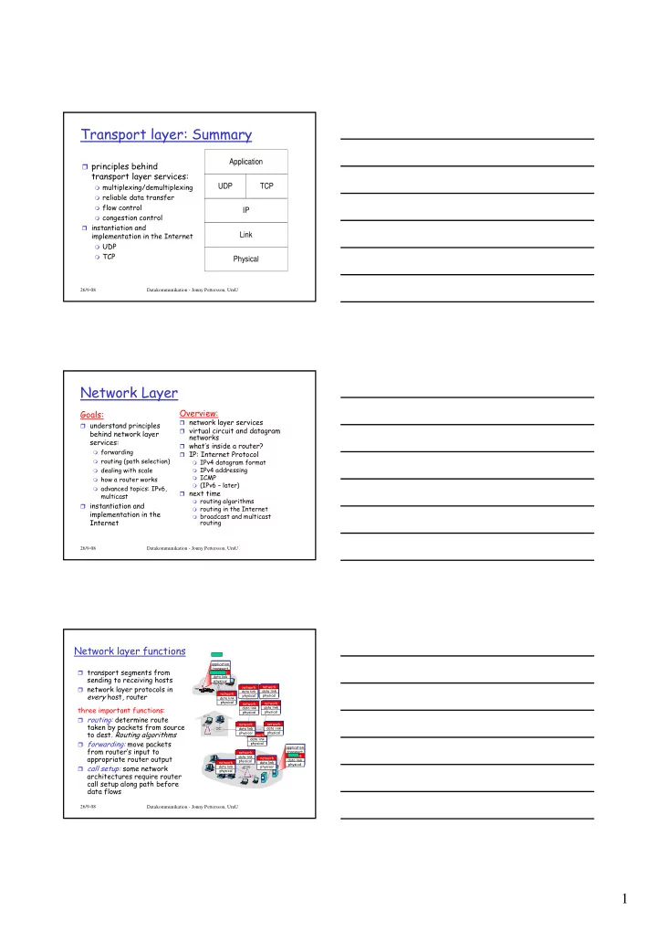
Network layer functions

transport segments from

sending to receiving hosts

network layer protocols in

every host, router three important functions:

routing: determine route

taken by packets from source to dest. Routing algorithms

forwarding: move packets

from router’s input to appropriate router output

call setup: some network

architectures require router call setup along path before data flows

application transport network data link physical application transport network data link physical network data link physical network data link physical network data link physical network data link physical network data link physical network data link physical network data link physical network data link physical network data link physical network data link physical network data link physical

slide-2
SLIDE 2

2

26/9-08 Datakommunikation - Jonny Pettersson, UmU

1

2 3

0111

value in arriving packet’s header

routing algorithm local forwarding table header value output link

0100 0101 0111 1001 3 2 2 1

Interplay between routing and forwarding

26/9-08 Datakommunikation - Jonny Pettersson, UmU

Network service model

Q: What service model for “channel” transporting datagrams from sender to receiver? Example services for individual datagrams:

guaranteed delivery guaranteed delivery

with less than 40 msec delay Example services for a flow of datagrams:

in-order datagram

delivery

guaranteed minimum

bandwidth to flow

restrictions on

changes in inter- packet spacing

26/9-08 Datakommunikation - Jonny Pettersson, UmU

Network layer service models:

Network Architecture Internet ATM ATM ATM ATM Service Model best effort CBR VBR ABR UBR Bandwidth none constant rate guaranteed rate guaranteed minimum none Loss no yes yes no no Order no yes yes yes yes Timing no yes yes no no Congestion feedback no (inferred via loss) no congestion no congestion yes no Guarantees ?

slide-3
SLIDE 3

3

26/9-08 Datakommunikation - Jonny Pettersson, UmU

Hur “förmedlar” man data?

Identifierare i headern

Virtual circuit (connection-oriented) Datagram (connectionless)

Vad krävs

Unika adresser Identifiera enskilda portar i en router/switch

26/9-08 Datakommunikation - Jonny Pettersson, UmU

Virtual Circuit Switching (VCS)

VC - Virtual circuit Tre steg

Uppkoppling (call setup)

  • permanent
  • via “signaler”

Dataöverföring Nedkoppling

Varje paket har en VC identifierare Varje router på vägen lagrar tillstånd för

varje koppling

Länk- och routerresurser kan allokerars

26/9-08 Datakommunikation - Jonny Pettersson, UmU

Virtual circuits: signaling protocols

used to setup, maintain, teardown VC used in ATM, frame-relay, X.25 not used in today’s Internet (~) application transport network data link physical application transport network data link physical

  • 1. Initiate call
  • 2. incoming call
  • 3. Accept call
  • 4. Call connected
  • 5. Data flow begins
  • 6. Receive data
slide-4
SLIDE 4

4

26/9-08 Datakommunikation - Jonny Pettersson, UmU

Kännetecken för VCS

Minst 1 RTT fördröjning vid uppkoppling Liten OH för varje datapaket Vid fel, riv allt och koppla nytt Hur vet switchen vägen till destinationen? När kopplingen är uppe

En väg finns Meddelanden kommer att skickas vidare Resursallokering

26/9-08

Datagram networks: the Internet model

Varje paket har info om destinationen, ingen call setup Routers har inga “tillstånd” “Forwarding” tabell, uppdateras av bakgrundsprocess Kännetecken

Paket kan skickas när som helst och var som helst Sändaren vet inte om paketet kan levereras Paket hanteras oberoende av varandra Kan hitta vägar runt problem

application transport network data link physical application transport network data link physical

  • 1. Send data
  • 2. Receive data

26/9-08 Datakommunikation - Jonny Pettersson, UmU

Forwarding table

Destination Address Range Link Interface 11001000 00010111 00010000 00000000 through 11001000 00010111 00010111 11111111 11001000 00010111 00011000 00000000 through 1 11001000 00010111 00011000 11111111 11001000 00010111 00011001 00000000 through 2 11001000 00010111 00011111 11111111

  • therwise

3

4 billion possible entries

slide-5
SLIDE 5

5

26/9-08 Datakommunikation - Jonny Pettersson, UmU

Longest prefix matching

Prefix Match Link Interface 11001000 00010111 00010 11001000 00010111 00011000 1 11001000 00010111 00011 2

  • therwise

3 DA: 11001000 00010111 00011000 10101010 Examples DA: 11001000 00010111 00010110 10100001 Which interface? Which interface?

26/9-08 Datakommunikation - Jonny Pettersson, UmU

Datagram eller VC nätverk

Contention

Flera paket vill till samma länk samtidigt

Congestion

När köerna i routern är fulla och paket börjar slängas

Datagram

Bryr sig inte, kontroll högre upp Högt utnyttjande Smarta ändsystem

VCS

“Hop-by-hop” flödeskontroll Konservativt QoS Dumma ändsystem 26/9-08 Datakommunikation - Jonny Pettersson, UmU

Router Architecture Overview

Two key router functions:

run routing algorithms/protocol (RIP, OSPF, BGP) forwarding datagrams from incoming to outgoing link

slide-6
SLIDE 6

6

26/9-08 Datakommunikation - Jonny Pettersson, UmU

Input Port Functions

Decentralized switching:

given datagram dest., lookup output port

using routing table in input port memory

goal: complete input port processing at

‘line speed’

queuing: if datagrams arrive faster than

forwarding rate into switch fabric Physical layer: bit-level reception Data link layer: e.g., Ethernet see chapter 5

26/9-08 Datakommunikation - Jonny Pettersson, UmU

Input Port Queuing

Fabric slower than input ports combined -> queueing

may occur at input queues

Head-of-the-Line (HOL) blocking: queued datagram

at front of queue prevents others in queue from moving forward

queueing delay and loss due to input buffer overflow!

26/9-08

Three types of switching fabrics

Via memory First generation routers:

packet copied

by system’s (single) CPU

speed limited

by memory bandwidth (2 bus crossings per datagram) Modern routers:

input port

processor performs lookup, copy into memory in

  • utput port

Via bus

datagram

from input port memory to output port memory via a shared bus

bus

contention: switching speed limited by bus bandwidth Via an interconection network

  • vercome bus bandwidth

limitations

Advanced design:

fragmenting datagram into fixed length cells, switch cells through the fabric

slide-7
SLIDE 7

7

26/9-08 Datakommunikation - Jonny Pettersson, UmU

Output Ports

Buffering required when datagrams arrive from

fabric faster than the transmission rate

Scheduling discipline chooses among queued

datagrams for transmission

26/9-08 Datakommunikation - Jonny Pettersson, UmU

Output port queueing

buffering when arrival rate via switch exceeds

  • utput line speed

queueing (delay) and loss due to output port

buffer overflow!

26/9-08 Datakommunikation - Jonny Pettersson, UmU

How much buffering?

RFC 3439 rule of thumb: average buffering

equal to “typical” RTT (say 250 msec) times link capacity C

e.g., C = 10 Gps link: 2.5 Gbit buffer

Recent recommendation: with N flows,

buffering equal to RTT C

.

N

slide-8
SLIDE 8

8

26/9-08 Datakommunikation - Jonny Pettersson, UmU

The Internet Network layer

forwarding table

Host, router network layer functions:

Routing protocols

  • path selection
  • RIP, OSPF, BGP

IP protocol

  • addressing conventions
  • datagram format
  • packet handling conventions

ICMP protocol

  • error reporting
  • router “signaling”

Transport layer: TCP, UDP Link layer physical layer

Network layer

IP datagram format

ver length 32 bits

data (variable length, typically a TCP

  • r UDP segment)

16-bit identifier header checksum time to live 32 bit source IP address IP protocol version number header length (bytes) max number remaining hops (decremented at each router) for fragmentation/ reassembly total datagram length (bytes) upper layer protocol to deliver payload to head. len type of service “type” of data flgs fragment

  • ffset

upper layer 32 bit destination IP address Options (if any) E.g. timestamp, record route taken, specify list of routers to visit

how much overhead with TCP?

20 bytes of TCP 20 bytes of IP = 40 bytes + app

layer overhead

26/9-08 Datakommunikation - Jonny Pettersson, UmU

Fragmentering och hopsättning

MTU varierar i olika nät, två val

Alla paket tillräckligt små Fragmentering och hopsättning

Alla fragment har samma Ident Tappas ett fragment slängs alla Varje fragment fullständigt IP-datagram Hopsättning hos mottagaren Designat för ytterligare fragmentering

Ident Flags Offset

slide-9
SLIDE 9

9

26/9-08 Datakommunikation - Jonny Pettersson, UmU

IP Fragmentation and Reassembly

ID =x

  • ffset

=0 fragflag =0 length =4000 ID =x

  • ffset

=0 fragflag =1 length =1500 ID =x

  • ffset

=185 fragflag =1 length =1500 ID =x

  • ffset

=370 fragflag =0 length =1040 One large datagram becomes several smaller datagrams

Example

4000 byte

datagram

MTU = 1500 bytes 1480 bytes in data field

  • ffset =

1480/8

26/9-08 Datakommunikation - Jonny Pettersson, UmU

IP Addressing: introduction

IP address: 32-bit

identifier for host, router interface

interface: connection

between host/router and physical link

router’s typically have

multiple interfaces

host may have multiple

interfaces

IP addresses

associated with each interface

223.1.1.1 223.1.1.2 223.1.1.3 223.1.1.4 223.1.2.9 223.1.2.2 223.1.2.1 223.1.3.2 223.1.3.1 223.1.3.27 223.1.1.1 = 11011111 00000001 00000001 00000001 223 1 1 1

26/9-08 Datakommunikation - Jonny Pettersson, UmU

IP Addresses - earlier

0network host 10 network host 110 network host 1110 multicast address

A B C D class

1.0.0.0 to 127.255.255.255 128.0.0.0 to 191.255.255.255 192.0.0.0 to 223.255.255.255 224.0.0.0 to 239.255.255.255

32 bits

“class-full” addressing:

slide-10
SLIDE 10

10

26/9-08 Datakommunikation - Jonny Pettersson, UmU

IP addressing: CIDR

CIDR: Classless InterDomain Routing

subnet portion of address of arbitrary length address format: a.b.c.d/x, where x is # bits in

subnet portion of address 11001000 00010111 00010000 00000000

subnet part host part

200.23.16.0/23

26/9-08 Datakommunikation - Jonny Pettersson, UmU

Subnets

IP address:

subnet part (high

  • rder bits)

host part (low order

bits) What’s a subnet ?

device interfaces with

same subnet part of IP address

can physically reach

each other without intervening router

223.1.1.1 223.1.1.2 223.1.1.3 223.1.1.4 223.1.2.9 223.1.2.2 223.1.2.1 223.1.3.2 223.1.3.1 223.1.3.27

network consisting of 3 subnets LAN

223.1.1.0/24 223.1.2.0/24 223.1.3.0/24 Subnet mask: /24

26/9-08 Datakommunikation - Jonny Pettersson, UmU

Speciella adresser

Nätverksadresser har HostId fylld med 0 127/8 - Reserverad för loopback 0.0.0.0 - Den här maskinen Bara 1’or - Broadcast i lokalt nät Bara 1’or i HostId - Broadcast i SubnetId Det krävs en IP-adress för varje interface

i en maskin

slide-11
SLIDE 11

11

26/9-08 Datakommunikation - Jonny Pettersson, UmU

Svagheter i Internetadresseringen

Om en maskin flyttas måste också adresser

bytas

Rutten baseras på adressen - vägen till en

multi-homed host påverkas av adressen

26/9-08 Datakommunikation - Jonny Pettersson, UmU

IP addresses: how to get one?

Q: How does a host get IP address?

hard-coded by system admin in a file

Windows: control-panel->network->configuration-

>tcp/ip->properties

UNIX: /etc/rc.config

DHCP: Dynamic Host Configuration Protocol:

dynamically get address from as server

“plug-and-play”

26/9-08 Datakommunikation - Jonny Pettersson, UmU

DHCP: Dynamic Host Configuration Protocol

Goal: allow host to dynamically obtain its IP address from network server when it joins network

Can renew its lease on address in use Allows reuse of addresses (only hold address while connected and “on”) Support for mobile users who want to join network (more shortly)

DHCP overview:

host broadcasts “DHCP discover” msg DHCP server responds with “DHCP offer” msg host requests IP address: “DHCP request” msg DHCP server sends address: “DHCP ack” msg

slide-12
SLIDE 12

12

26/9-08 Datakommunikation - Jonny Pettersson, UmU

DHCP client-server scenario

223.1.1.1 223.1.1.2 223.1.1.3 223.1.1.4 223.1.2.9 223.1.2.2 223.1.2.1 223.1.3.2 223.1.3.1 223.1.3.27

A B E

DHCP server arriving DHCP client needs address in this network

26/9-08 Datakommunikation - Jonny Pettersson, UmU

DHCP

26/9-08 Datakommunikation - Jonny Pettersson, UmU

IP addresses: how to get one?

Q: How does network get subnet part of IP address? A: gets allocated portion of its provider ISP’s address space

ISP's block 11001000 00010111 00010000 00000000 200.23.16.0/20 Organization 0 11001000 00010111 00010000 00000000 200.23.16.0/23 Organization 1 11001000 00010111 00010010 00000000 200.23.18.0/23 Organization 2 11001000 00010111 00010100 00000000 200.23.20.0/23 ... ….. …. …. Organization 7 11001000 00010111 00011110 00000000 200.23.30.0/23

slide-13
SLIDE 13

13

26/9-08 Datakommunikation - Jonny Pettersson, UmU

Hierarchical addressing: route aggregation

“Send me anything with addresses beginning 200.23.16.0/20”

200.23.16.0/23 200.23.18.0/23 200.23.30.0/23

Fly-By-Night-ISP Organization 0 Organization 7 Internet Organization 1 ISPs-R-Us “Send me anything with addresses beginning 199.31.0.0/16”

200.23.20.0/23

Organization 2

. . . . . .

Hierarchical addressing allows efficient advertisement of routing information:

26/9-08 Datakommunikation - Jonny Pettersson, UmU

Hierarchical addressing: more specific routes

ISPs-R-Us has a more specific route to Organization 1

“Send me anything with addresses beginning 200.23.16.0/20”

200.23.16.0/23 200.23.18.0/23 200.23.30.0/23

Fly-By-Night-ISP Organization 0 Organization 7 Internet Organization 1 ISPs-R-Us “Send me anything with addresses beginning 199.31.0.0/16

  • r 200.23.18.0/23”

200.23.20.0/23

Organization 2

. . . . . .

26/9-08 Datakommunikation - Jonny Pettersson, UmU

IP addressing: the last word...

Q: How does an ISP get block of addresses? A: ICANN: Internet Corporation for Assigned

Names and Numbers

allocates addresses manages DNS root servers assigns domain names, resolves disputes in Europe delegated to RIPE

slide-14
SLIDE 14

14

26/9-08 Datakommunikation - Jonny Pettersson, UmU

NAT: Network Address Translation

10.0.0.1 10.0.0.2 10.0.0.3 10.0.0.4 138.76.29.7

local network (e.g., home network) 10.0.0/24 rest of Internet

Datagrams with source or destination in this network have 10.0.0/24 address for source, destination (as usual) All datagrams leaving local network have same single source NAT IP address: 138.76.29.7, different source port numbers

26/9-08 Datakommunikation - Jonny Pettersson, UmU

NAT: Network Address Translation

Motivation: local network uses just one IP address as

far as outside world is concerned:

no need to be allocated range of addresses from ISP:

  • just one IP address is used for all devices

can change addresses of devices in local network

without notifying outside world

can change ISP without changing addresses of

devices in local network

devices inside local net not explicitly addressable,

visible by outside world (a security plus)

26/9-08 Datakommunikation - Jonny Pettersson, UmU

NAT: Network Address Translation

Implementation: NAT router must:

  • utgoing datagrams: replace (source IP address, port

#) of every outgoing datagram to (NAT IP address, new port #) . . . remote clients/servers will respond using (NAT IP address, new port #) as destination addr.

remember (in NAT translation table) every (source

IP address, port #) to (NAT IP address, new port #) translation pair

incoming datagrams: replace (NAT IP address, new

port #) in dest fields of every incoming datagram with corresponding (source IP address, port #) stored in NAT table

slide-15
SLIDE 15

15

26/9-08 Datakommunikation - Jonny Pettersson, UmU

NAT: Network Address Translation

10.0.0.1 10.0.0.2 10.0.0.3

S: 10.0.0.1, 3345 D: 128.119.40.186, 80

1

10.0.0.4 138.76.29.7

1: host 10.0.0.1 sends datagram to 128.119.40.186, 80 NAT translation table WAN side addr LAN side addr 138.76.29.7, 5001 10.0.0.1, 3345 …… ……

S: 128.119.40.186, 80 D: 10.0.0.1, 3345

4

S: 138.76.29.7, 5001 D: 128.119.40.186, 80

2 2: NAT router changes datagram source addr from 10.0.0.1, 3345 to 138.76.29.7, 5001, updates table

S: 128.119.40.186, 80 D: 138.76.29.7, 5001

3 3: Reply arrives

  • dest. address:

138.76.29.7, 5001 4: NAT router changes datagram dest addr from 138.76.29.7, 5001 to 10.0.0.1, 3345

26/9-08 Datakommunikation - Jonny Pettersson, UmU

NAT: Network Address Translation

16-bit port-number field:

60,000 simultaneous connections with a single

LAN-side address! NAT is controversial:

routers should only process up to layer 3 violates end-to-end argument

  • NAT possibility must be taken into account by app

designers, eg, P2P applications

address shortage should instead be solved by

IPv6

26/9-08 Datakommunikation - Jonny Pettersson, UmU

NAT traversal problem

client wants to connect to

server with address 10.0.0.1

server address 10.0.0.1 local

to LAN (client can’t use it as destination addr)

  • nly one externally visible

NATted address: 138.76.29.7 solution 1: statically

configure NAT to forward incoming connection requests at given port to server

e.g., (123.76.29.7, port 2500)

always forwarded to 10.0.0.1 port 25000

10.0.0.1 10.0.0.4

NAT router

138.76.29.7

Client ?

slide-16
SLIDE 16

16

26/9-08 Datakommunikation - Jonny Pettersson, UmU

NAT traversal problem

solution 2: Universal Plug and

Play (UPnP) Internet Gateway Device (IGD) Protocol. Allows NATted host to:

learn public IP address

(138.76.29.7)

add/remove port mappings

(with lease times) i.e., automate static NAT port map configuration

10.0.0.1 10.0.0.4

NAT router

138.76.29.7

IGD

26/9-08 Datakommunikation - Jonny Pettersson, UmU

NAT traversal problem

solution 3: relaying (used in Skype)

NATed client establishes connection to relay external client connects to relay relay bridges packets between connections

138.76.29.7

Client

10.0.0.1

NAT router

  • 1. connection to

relay initiated by NATted host

  • 2. connection to

relay initiated by client

  • 3. relaying

established

26/9-08 Datakommunikation - Jonny Pettersson, UmU

ICMP: Internet Control Message Protocol

used by hosts & routers to

communicate network-level information

error reporting:

unreachable host, network, port, protocol

echo request/reply (used

by ping)

network-layer “above” IP: ICMP msgs carried in IP

datagrams

ICMP message: type, code plus

first 8 bytes of IP datagram causing error Type Code description 0 0 echo reply (ping) 3 0 dest. network unreachable 3 1 dest host unreachable 3 2 dest protocol unreachable 3 3 dest port unreachable 3 6 dest network unknown 3 7 dest host unknown 4 0 source quench (congestion control - not used) 8 0 echo request (ping) 9 0 route advertisement 10 0 router discovery 11 0 TTL expired 12 0 bad IP header

slide-17
SLIDE 17

17

26/9-08 Datakommunikation - Jonny Pettersson, UmU

Traceroute and ICMP

Source sends series of

UDP segments to dest

First has TTL =1 Second has TTL=2, etc. Unlikely port number

When nth datagram arrives

to nth router:

Router discards datagram And sends to source an

ICMP message (type 11, code 0)

Message includes name of

router & IP address When ICMP message

arrives, source calculates RTT

Traceroute does this 3

times Stopping criterion

UDP segment eventually

arrives at destination host

Destination returns ICMP

“dest port unreachable” packet (type 3, code 3)

When source gets this

ICMP, stops

26/9-08 Datakommunikation - Jonny Pettersson, UmU

Summary

network layer services virtual circuit and

datagram networks

what’s inside a router? IP: Internet Protocol

IPv4 datagram format IPv4 addressing ICMP

next time

routing algorithms routing in the Internet broadcast and multicast

routing