
1
7/5-07 Datakommunikation - Jonny Pettersson, UmU
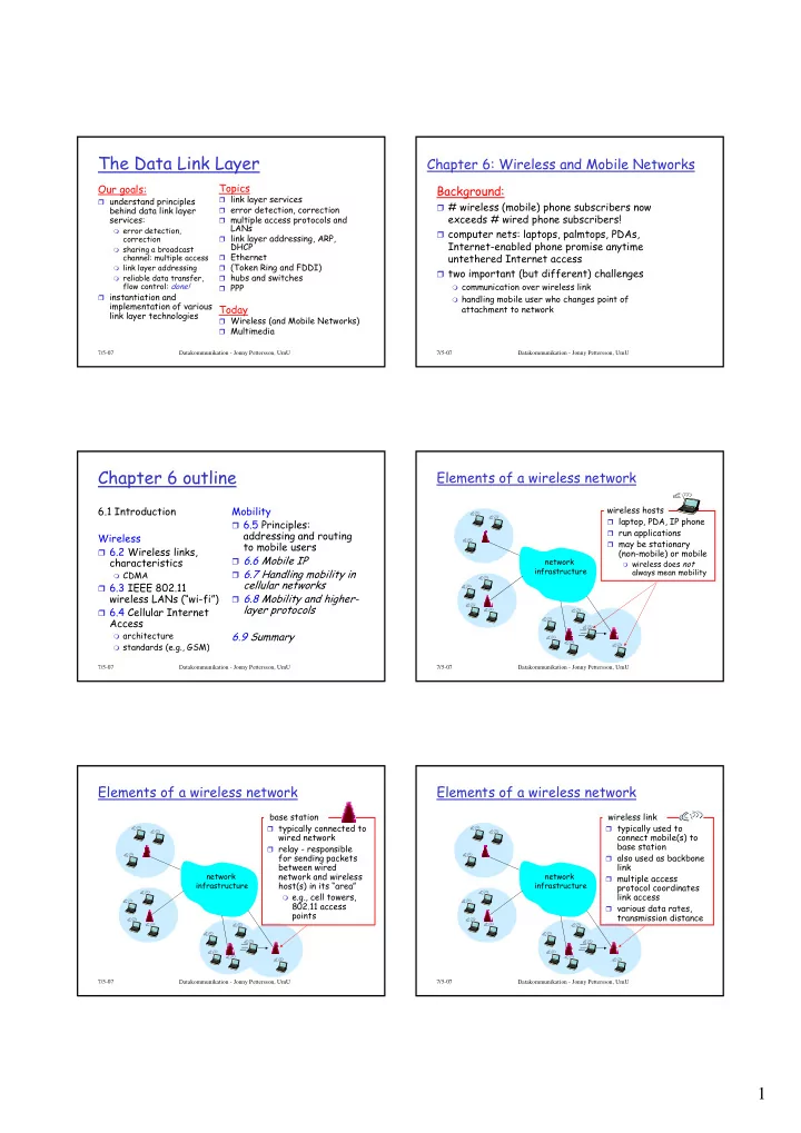
The Data Link Layer
Our goals:
understand principles
behind data link layer services:
error detection,
correction
sharing a broadcast
channel: multiple access
link layer addressing reliable data transfer,
flow control: done! instantiation and
implementation of various link layer technologies
Topics
link layer services error detection, correction multiple access protocols and
LANs
link layer addressing, ARP,
DHCP
Ethernet (Token Ring and FDDI) hubs and switches PPP
Today
Wireless (and Mobile Networks) Multimedia
7/5-07 Datakommunikation - Jonny Pettersson, UmU
Chapter 6: Wireless and Mobile Networks
Background:
# wireless (mobile) phone subscribers now
exceeds # wired phone subscribers!
computer nets: laptops, palmtops, PDAs,
Internet-enabled phone promise anytime untethered Internet access
two important (but different) challenges
communication over wireless link handling mobile user who changes point of
attachment to network
7/5-07 Datakommunikation - Jonny Pettersson, UmU
Chapter 6 outline
6.1 Introduction Wireless
6.2 Wireless links,
characteristics
CDMA
6.3 IEEE 802.11
wireless LANs (“wi-fi”)
6.4 Cellular Internet
Access
architecture standards (e.g., GSM)
Mobility
6.5 Principles:
addressing and routing to mobile users
6.6 Mobile IP 6.7 Handling mobility in
cellular networks
6.8 Mobility and higher-
layer protocols 6.9 Summary
7/5-07 Datakommunikation - Jonny Pettersson, UmU
Elements of a wireless network
network infrastructure
wireless hosts
laptop, PDA, IP phone run applications may be stationary
(non-mobile) or mobile
wireless does not
always mean mobility
7/5-07 Datakommunikation - Jonny Pettersson, UmU
Elements of a wireless network
network infrastructure
base station
typically connected to
wired network
relay - responsible
for sending packets between wired network and wireless host(s) in its “area”
e.g., cell towers,
802.11 access points
7/5-07 Datakommunikation - Jonny Pettersson, UmU
Elements of a wireless network
network infrastructure
wireless link
typically used to
connect mobile(s) to base station
also used as backbone
link
multiple access
protocol coordinates link access
various data rates,
transmission distance