1 Direct Memory Access (DMA) operation Hardwares view of interrupts - - PDF document

1
SMART_READER_LITE
LIVE PREVIEW

1 Direct Memory Access (DMA) operation Hardwares view of interrupts - - PDF document

Input/Output Principles of I/O hardware Principles of I/O software Chapter 5: I/O Systems I/O software layers Disks Clocks Character-oriented terminals Graphical user interfaces Network terminals Power management


slide-1
SLIDE 1

1

Chapter 5: I/O Systems

Chapter 5 2 CS 1550, cs.pitt.edu (originaly modified by Ethan L. Miller and Scott A. Brandt)

Input/Output

Principles of I/O hardware Principles of I/O software I/O software layers Disks Clocks Character-oriented terminals Graphical user interfaces Network terminals Power management

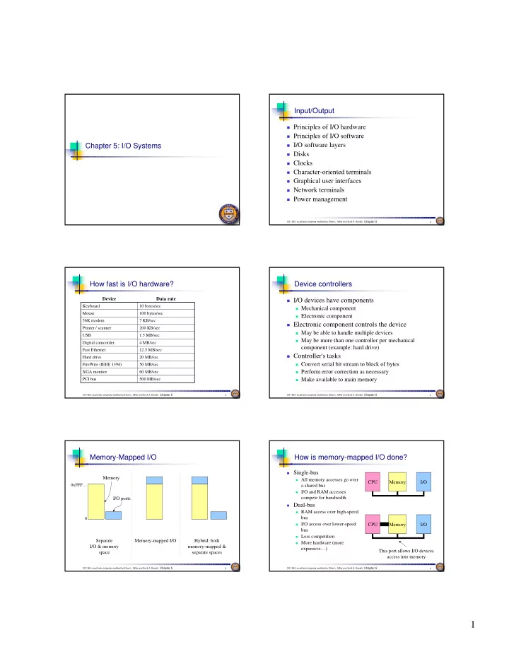
Chapter 5 3 CS 1550, cs.pitt.edu (originaly modified by Ethan L. Miller and Scott A. Brandt)

How fast is I/O hardware?

4 MB/sec Digital camcorder 500 MB/sec PCI bus 60 MB/sec XGA monitor 50 MB/sec FireWire (IEEE 1394) 20 MB/sec Hard drive 12.5 MB/sec Fast Ethernet 1.5 MB/sec USB 200 KB/sec Printer / scanner 7 KB/sec 56K modem 100 bytes/sec Mouse 10 bytes/sec Keyboard

Data rate Device

Chapter 5 4 CS 1550, cs.pitt.edu (originaly modified by Ethan L. Miller and Scott A. Brandt)

Device controllers

I/O devices have components

Mechanical component Electronic component

Electronic component controls the device

May be able to handle multiple devices May be more than one controller per mechanical

component (example: hard drive)

Controller's tasks

Convert serial bit stream to block of bytes Perform error correction as necessary Make available to main memory

Chapter 5 5 CS 1550, cs.pitt.edu (originaly modified by Ethan L. Miller and Scott A. Brandt)

Memory-Mapped I/O

Separate I/O & memory space

0xFFF…

Memory I/O ports Memory-mapped I/O Hybrid: both memory-mapped & separate spaces

Chapter 5 6 CS 1550, cs.pitt.edu (originaly modified by Ethan L. Miller and Scott A. Brandt)

How is memory-mapped I/O done?

Single-bus

All memory accesses go over

a shared bus

I/O and RAM accesses

compete for bandwidth

Dual-bus

RAM access over high-speed

bus

I/O access over lower-speed

bus

Less competition More hardware (more

expensive…) CPU Memory I/O CPU Memory I/O This port allows I/O devices access into memory

slide-2
SLIDE 2

2

Chapter 5 7 CS 1550, cs.pitt.edu (originaly modified by Ethan L. Miller and Scott A. Brandt)

Direct Memory Access (DMA) operation

Chapter 5 8 CS 1550, cs.pitt.edu (originaly modified by Ethan L. Miller and Scott A. Brandt)

Hardware’s view of interrupts

Bus

Chapter 5 9 CS 1550, cs.pitt.edu (originaly modified by Ethan L. Miller and Scott A. Brandt)

I/O software: goals

Device independence

Programs can access any I/O device No need to specify device in advance

Uniform naming

Name of a file or device is a string or an integer Doesn’t depend on the machine (underlying hardware)

Error handling

Done as close to the hardware as possible Isolate higher-level software

Synchronous vs. asynchronous transfers

Blocked transfers vs. interrupt-driven

Buffering

Data coming off a device cannot be stored in final destination

Sharable vs. dedicated devices

Chapter 5 10 CS 1550, cs.pitt.edu (originaly modified by Ethan L. Miller and Scott A. Brandt)

Programmed I/O: printing a page

Printed page ABCD EFG H

Kernel User

A Printed page ABCD EFG H ABCD EFG H AB Printed page ABCD EFG H ABCD EFG H

Chapter 5 11 CS 1550, cs.pitt.edu (originaly modified by Ethan L. Miller and Scott A. Brandt)

Code for programmed I/O

copy_from_user (buffer, p, count); // copy into kernel buffer for (j = 0; j < count; j++) { // loop for each char while (*printer_status_reg != READY) ; // wait for printer to be ready *printer_data_reg = p[j]; // output a single character } return_to_user();

Chapter 5 12 CS 1550, cs.pitt.edu (originaly modified by Ethan L. Miller and Scott A. Brandt)

Interrupt-driven I/O

copy_from_user (buffer, p, count); j = 0; enable_interrupts(); while (*printer_status_reg != READY) ; *printer_data_reg = p[0]; scheduler(); // and block user if (count == 0) { unblock_user(); } else { *printer_data_reg = p[j]; count--; j++; } acknowledge_interrupt(); return_from_interrupt();

Code run by system call Code run at interrupt time

slide-3
SLIDE 3

3

Chapter 5 13 CS 1550, cs.pitt.edu (originaly modified by Ethan L. Miller and Scott A. Brandt)

I/O using DMA

copy_from_user (buffer, p, count); set_up_DMA_controller(); scheduler(); // and block user acknowledge_interrupt(); unblock_user(); return_from_interrupt();

Code run by system call Code run at interrupt time

Chapter 5 14 CS 1550, cs.pitt.edu (originaly modified by Ethan L. Miller and Scott A. Brandt)

Layers of I/O software

User-level I/O software & libraries Device-independent OS software Device drivers Interrupt handlers Hardware Operating system (kernel) User

Chapter 5 15 CS 1550, cs.pitt.edu (originaly modified by Ethan L. Miller and Scott A. Brandt)

Interrupt handlers

Interrupt handlers are best hidden

Driver starts an I/O operation and blocks Interrupt notifies of completion

Interrupt procedure does its task

Then unblocks driver that started it Perform minimal actions at interrupt time

Some of the functionality can be done by the driver after it is

unblocked

Interrupt handler must

Save regs not already saved by interrupt hardware Set up context for interrupt service procedure DLXOS: intrhandler (in dlxos.s)

Chapter 5 16 CS 1550, cs.pitt.edu (originaly modified by Ethan L. Miller and Scott A. Brandt)

What happens on an interrupt

Set up stack for interrupt service procedure Ack interrupt controller, reenable interrupts Copy registers from where saved Run service procedure (optional) Pick a new process to run next Set up MMU context for process to run next Load new process' registers Start running the new process

Chapter 5 17 CS 1550, cs.pitt.edu (originaly modified by Ethan L. Miller and Scott A. Brandt)

Device drivers

Device drivers go between

device controllers and rest

  • f OS
Drivers standardize interface

to widely varied devices

Device drivers

communicate with controllers over bus

Controllers communicate

with devices themselves User space Kernel space

User program Keyboard driver Disk driver Rest of the OS

Keyboard controller Disk controller

Chapter 5 18 CS 1550, cs.pitt.edu (originaly modified by Ethan L. Miller and Scott A. Brandt)

Device-independent I/O software

Device-independent I/O software provides common

“library” routines for I/O software

Helps drivers maintain a standard appearance to the

rest of the OS

Uniform interface for many device drivers for

Buffering Error reporting Allocating and releasing dedicated devices Suspending and resuming processes

Common resource pool

Device-independent block size (keep track of blocks) Other device driver resources

slide-4
SLIDE 4

4

Chapter 5 19 CS 1550, cs.pitt.edu (originaly modified by Ethan L. Miller and Scott A. Brandt)

Why a standard driver interface?

Non-standard driver interfaces Standard driver interfaces

Chapter 5 20 CS 1550, cs.pitt.edu (originaly modified by Ethan L. Miller and Scott A. Brandt)

Buffering device input

User space Kernel space User space Kernel space User space Kernel space User space Kernel space

Unbuffered input Buffering in user space Buffer in kernel Copy to user space Double buffer in kernel

1 2 1 3 2

Chapter 5 21 CS 1550, cs.pitt.edu (originaly modified by Ethan L. Miller and Scott A. Brandt)

Anatomy of an I/O request

Chapter 5 22 CS 1550, cs.pitt.edu (originaly modified by Ethan L. Miller and Scott A. Brandt)

Disk drive structure

sector cylinder platter spindle track head actuator surfaces

Data stored on surfaces

Up to two surfaces per platter One or more platters per disk

Data in concentric tracks

Tracks broken into sectors 256B-1KB per sector Cylinder: corresponding

tracks on all surfaces

Data read and written by

heads

Actuator moves heads Heads move in unison Chapter 5 23 CS 1550, cs.pitt.edu (originaly modified by Ethan L. Miller and Scott A. Brandt)

Disk drive specifics

17 µsec 22 ms Sector transfer time 20 sec 250 ms Spinup time 8.33 ms 200 ms Rotation time 6.9 ms 77 ms Seek time (average) 0.8 ms 6 ms Seek time (minimum) 18.3 GB 360 KB Capacity 512 512 Bytes per sector 35742000 720 Sectors per disk 281 (average) 9 Sectors per track 12 2 Tracks per cylinder 10601 40 Cylinders

WD 18GB HD IBM 360KB floppy

Chapter 5 24 CS 1550, cs.pitt.edu (originaly modified by Ethan L. Miller and Scott A. Brandt)

Disk “zones”

Outside tracks are longer

than inside tracks

Two options

Bits are “bigger” More bits (transfer faster)

Modern hard drives use

second option

More data on outer tracks

Disk divided into “zones”

Constant sectors per track in

each zone

8–20 (or more) zones on a

disk

slide-5
SLIDE 5

5

Chapter 5 25 CS 1550, cs.pitt.edu (originaly modified by Ethan L. Miller and Scott A. Brandt)

Disk “addressing”

Millions of sectors on the disk must be labeled Two possibilities

Cylinder/track/sector Sequential numbering

Modern drives use sequential numbers

Disks map sequential numbers into specific location Mapping may be modified by the disk

Remap bad sectors Optimize performance

Hide the exact geometry, making life simpler for the OS

Chapter 5 26 CS 1550, cs.pitt.edu (originaly modified by Ethan L. Miller and Scott A. Brandt)

Building a better “disk”

Problem: CPU performance has been increasing

exponentially, but disk performance hasn’t

Disks are limited by mechanics

Problem: disks aren’t all that reliable Solution: distribute data across disks, and use some

  • f the space to improve reliability

Data transferred in parallel Data stored across drives (striping) Parity on an “extra” drive for reliability

Chapter 5 27 CS 1550, cs.pitt.edu (originaly modified by Ethan L. Miller and Scott A. Brandt)

RAIDs, RAIDs, and more RAIDs

strip strip

Stripe

RAID 0 (Redudant Array of Inexpensive Disks RAID 1 (Mirrored copies) RAID 4 (Striped with parity) RAID 5 (Parity rotates through disks)

Chapter 5 28 CS 1550, cs.pitt.edu (originaly modified by Ethan L. Miller and Scott A. Brandt)

CD-ROM recording

CD-ROM has data in a

spiral

Hard drives have concentric

circles of data

One continuous track: just

like vinyl records!

Pits & lands “simulated”

with heat-sensitive material

  • n CD-Rs and CD-RWs
Chapter 5 29 CS 1550, cs.pitt.edu (originaly modified by Ethan L. Miller and Scott A. Brandt)

Structure of a disk sector

Preamble contains information about the sector

Sector number & location information

Data is usually 256, 512, or 1024 bytes ECC (Error Correcting Code) is used to detect & correct

minor errors in the data

Preamble Data ECC

Chapter 5 30 CS 1550, cs.pitt.edu (originaly modified by Ethan L. Miller and Scott A. Brandt)

Sector layout on disk

Sectors numbered

sequentially on each track

Numbering starts in

different place on each track: sector skew

Allows time for switching

head from track to track

All done to minimize delay

in sequential transfers

slide-6
SLIDE 6

6

Chapter 5 31 CS 1550, cs.pitt.edu (originaly modified by Ethan L. Miller and Scott A. Brandt)

Sector interleaving

On older systems, the CPU was slow => time elapsed

between reading consecutive sectors

Solution: leave space between consecutively numbered

sectors

This isn’t done much these days…

1 2 3 4 5 6 7 4 1 5 2 6 3 7 3 6 1 4 7 2 5

No interleaving Skipping 1 sector Skipping 2 sectors

Chapter 5 32 CS 1550, cs.pitt.edu (originaly modified by Ethan L. Miller and Scott A. Brandt)

What’s in a disk request?

Time required to read or write a disk block

determined by 3 factors

Seek time Rotational delay

Average delay = 1/2 rotation time Example: rotate in 10ms, average rotation delay = 5ms

Actual transfer time

Transfer time = time to rotate over sector Example: rotate in 10ms, 200 sectors/track => 10/200 ms =

0.05ms transfer time per sector

Seek time dominates, with rotation time close Error checking is done by controllers

Chapter 5 33 CS 1550, cs.pitt.edu (originaly modified by Ethan L. Miller and Scott A. Brandt)

Disk request scheduling

Goal: use disk hardware efficiently

Bandwidth as high as possible Disk transferring as often as possible (and not seeking)

We want to

Minimize disk seek time (moving from track to track) Minimize rotational latency (waiting for disk to rotate the desired

sector under the read/write head)

Calculate disk bandwidth by

Total bytes transferred / time to service request Seek time & rotational latency are overhead (no data is transferred),

and reduce disk bandwidth

Minimize seek time & rotational latency by

Using algorithms to find a good sequence for servicing requests Placing blocks of a given file “near” each other Chapter 5 34 CS 1550, cs.pitt.edu (originaly modified by Ethan L. Miller and Scott A. Brandt)

Disk scheduling algorithms

  • Schedule disk requests to minimize disk seek time
Seek time increases as distance increases (though not linearly) Minimize seek distance -> minimize seek time
  • Disk seek algorithm examples assume a request queue & head position

(disk has 200 cylinders)

Queue = 100, 175, 51, 133, 8, 140, 73, 77 Head position = 63

100 175 51 133 8 140 73 77 read/write head position disk requests (cylinder in which block resides) Outside edge Inside edge

Chapter 5 35 CS 1550, cs.pitt.edu (originaly modified by Ethan L. Miller and Scott A. Brandt)

First-Come-First Served (FCFS)

  • Requests serviced in the order in which they arrived
Easy to implement! May involve lots of unnecessary seek distance
  • Seek order = 100, 175, 51, 133, 8, 140, 73, 77
  • Seek distance = (100-63) + (175-100) + (175-51) + (133-51) +

(133-8) + (140-8) + (140-73) + (77-73) = 646 cylinders 100 175 51 133 8 140 73 77 read/write head start

Chapter 5 36 CS 1550, cs.pitt.edu (originaly modified by Ethan L. Miller and Scott A. Brandt)

Shortest Seek Time First (SSTF)

  • Service the request with the shortest seek time from the current head

position

Form of SJF scheduling May starve some requests
  • Seek order = 73, 77, 51, 8, 100, 133, 140, 175
  • Seek distance = 10 + 4 + 26 + 43 + 92 + 33 + 7 + 35 = 250 cylinders

100 175 51 133 8 140 73 77 read/write head start

slide-7
SLIDE 7

7

Chapter 5 37 CS 1550, cs.pitt.edu (originaly modified by Ethan L. Miller and Scott A. Brandt)

SCAN (elevator algorithm)

  • Disk arm starts at one end of the disk and moves towards the other end,

servicing requests as it goes

Reverses direction when it gets to end of the disk Also known as elevator algorithm
  • Seek order = 51, 8, 0 , 73, 77, 100, 133, 140, 175
  • Seek distance = 12 + 43 + 8 + 73 + 4 + 23 + 33 + 7 + 35 = 238 cyls

100 175 51 133 8 140 73 77 read/write head start

Chapter 5 38 CS 1550, cs.pitt.edu (originaly modified by Ethan L. Miller and Scott A. Brandt)

C-SCAN

  • Identical to SCAN, except head returns to cylinder 0 when it reaches the

end of the disk

Treats cylinder list as a circular list that wraps around the disk Waiting time is more uniform for cylinders near the edge of the disk
  • Seek order = 73, 77, 100, 133, 140, 175, 199, 0, 8, 51
  • Distance = 10 + 4 + 23 + 33 + 7 + 35 + 24 + 199 + 8 + 43 = 386 cyls

100 175 51 133 8 140 73 77 read/write head start

Chapter 5 39 CS 1550, cs.pitt.edu (originaly modified by Ethan L. Miller and Scott A. Brandt)

C-LOOK

  • Identical to C-SCAN, except head only travels as far as the last request in

each direction

Saves seek time from last sector to end of disk
  • Seek order = 73, 77, 100, 133, 140, 175, 8, 51
  • Distance = 10 + 4 + 23 + 33 + 7 + 35 + 167 + 43 = 322 cylinders

100 175 51 133 8 140 73 77 read/write head start

Chapter 5 40 CS 1550, cs.pitt.edu (originaly modified by Ethan L. Miller and Scott A. Brandt)

How to pick a disk scheduling algorithm

SSTF is easy to implement and works OK if there aren’t too

many disk requests in the queue

SCAN-type algorithms perform better for systems under

heavy load

More fair than SSTF Use LOOK rather than SCAN algorithms to save time

Long seeks aren’t too expensive, so choose C-LOOK over

LOOK to make response time more even

Disk request scheduling interacts with algorithms for

allocating blocks to files

Make scheduling algorithm modular: allow it to be changed without

changing the file system ⇒ Use SSTF for lightly loaded systems ⇒ Use C-LOOK for heavily loaded systems

Chapter 5 41 CS 1550, cs.pitt.edu (originaly modified by Ethan L. Miller and Scott A. Brandt)

When good disks go bad…

Disks have defects

In 3M+ sectors, this isn’t surprising!

ECC helps with errors, but sometimes this isn’t enough Disks keep spare sectors (normally unused) and remap bad

sectors into these spares

If there’s time, the whole track could be reordered… Chapter 5 42 CS 1550, cs.pitt.edu (originaly modified by Ethan L. Miller and Scott A. Brandt)

Clock hardware

slide-8
SLIDE 8

8

Chapter 5 43 CS 1550, cs.pitt.edu (originaly modified by Ethan L. Miller and Scott A. Brandt)

Maintaining time of day

Chapter 5 44 CS 1550, cs.pitt.edu (originaly modified by Ethan L. Miller and Scott A. Brandt)

Doing multiple timers with a single clock

Chapter 5 45 CS 1550, cs.pitt.edu (originaly modified by Ethan L. Miller and Scott A. Brandt)

Soft timers

A second clock may be available for timer interrupts

Specified by applications No problems if interrupt frequency is low

Soft timers avoid interrupts

Kernel checks for soft timer expiration before it exits to

user mode

How well this works depends on rate of kernel entries

Chapter 5 46 CS 1550, cs.pitt.edu (originaly modified by Ethan L. Miller and Scott A. Brandt)

Character-oriented terminals

An RS-232 terminal communicates with computer 1 bit at a

time

Called a serial line – bits go out in series, 1 bit at a time Windows uses COM1 and COM2 ports, first to serial lines Computer and terminal are completely independent

Chapter 5 47 CS 1550, cs.pitt.edu (originaly modified by Ethan L. Miller and Scott A. Brandt)

Buffering for input

Chapter 5 48 CS 1550, cs.pitt.edu (originaly modified by Ethan L. Miller and Scott A. Brandt)

Special terminal characters

slide-9
SLIDE 9

9

Chapter 5 49 CS 1550, cs.pitt.edu (originaly modified by Ethan L. Miller and Scott A. Brandt)

Special output characters

Chapter 5 50 CS 1550, cs.pitt.edu (originaly modified by Ethan L. Miller and Scott A. Brandt)

Driver writes directly into display's video RAM

Parallel port

Memory-mapped display

Chapter 5 51 CS 1550, cs.pitt.edu (originaly modified by Ethan L. Miller and Scott A. Brandt)
  • A video RAM image
simple monochrome display character mode
  • Corresponding screen
the xs are attribute bytes

How characters are displayed

Chapter 5 52 CS 1550, cs.pitt.edu (originaly modified by Ethan L. Miller and Scott A. Brandt)

Input software

Keyboard driver delivers a number

Driver converts to characters Uses a ASCII table

Exceptions, adaptations needed for other languages

Many OS provide for loadable keymaps or code pages Example: characters such as ç

Chapter 5 53 CS 1550, cs.pitt.edu (originaly modified by Ethan L. Miller and Scott A. Brandt)

Output software for Windows

Sample window located at (200,100) on XGA display

Chapter 5 54 CS 1550, cs.pitt.edu (originaly modified by Ethan L. Miller and Scott A. Brandt)

Skeleton of a Windows program

slide-10
SLIDE 10

10

Chapter 5 55 CS 1550, cs.pitt.edu (originaly modified by Ethan L. Miller and Scott A. Brandt)

Skeleton of a Windows program (cont’d)

Chapter 5 56 CS 1550, cs.pitt.edu (originaly modified by Ethan L. Miller and Scott A. Brandt)

Character outlines at different point sizes

Chapter 5 57 CS 1550, cs.pitt.edu (originaly modified by Ethan L. Miller and Scott A. Brandt)

X Windows

Chapter 5 58 CS 1550, cs.pitt.edu (originaly modified by Ethan L. Miller and Scott A. Brandt)

Architecture of the SLIM terminal system

Chapter 5 59 CS 1550, cs.pitt.edu (originaly modified by Ethan L. Miller and Scott A. Brandt)

The SLIM Network Terminal

Chapter 5 60 CS 1550, cs.pitt.edu (originaly modified by Ethan L. Miller and Scott A. Brandt)

Power Management (1)

Power consumption of various parts of a laptop computer

slide-11
SLIDE 11

11

Chapter 5 61 CS 1550, cs.pitt.edu (originaly modified by Ethan L. Miller and Scott A. Brandt)

Power management (2)

The use of zones for backlighting the display

Chapter 5 62 CS 1550, cs.pitt.edu (originaly modified by Ethan L. Miller and Scott A. Brandt)

Power Management (3)

Running at full clock speed Cutting voltage by two

cuts clock speed by two, cuts power by four

Chapter 5 63 CS 1550, cs.pitt.edu (originaly modified by Ethan L. Miller and Scott A. Brandt)

Power Management (4)

Telling the programs to use less energy

may mean poorer user experience

Examples

change from color output to black and white speech recognition reduces vocabulary less resolution or detail in an image