1 Connectionless demultiplexing How demultiplexing works host - - PDF document

1
SMART_READER_LITE
LIVE PREVIEW

1 Connectionless demultiplexing How demultiplexing works host - - PDF document

Goals Understand transport services Multiplexing and Demultiplexing Transport Overview and UDP Reliable data transfer Flow control Congestion control TCP and UDP Transport Layer Transport Layer 3-1 3-2 Transport


slide-1
SLIDE 1

1

Transport Layer 3-1

Transport Overview and UDP

Transport Layer 3-2

Goals

❒ Understand transport services

❍ Multiplexing and Demultiplexing ❍ Reliable data transfer ❍ Flow control ❍ Congestion control

❒ TCP and UDP

Transport Layer 3-3

Transport services and protocols

❒ provide logical communication

between app processes running on different hosts

❒ transport protocols run in

end systems

❍ send side: breaks app

messages into segments, passes to network layer

❍ rcv side: reassembles

segments into messages, passes to app layer

❒ more than one transport

protocol available to apps

❍ Internet: TCP and UDP

applicatio n transport network data link physical applicatio n transport network data link physical network data link physical network data link physical network data link physical network data link physical network data link physical

logical end-end transport

Transport Layer 3-4

Transport vs. network layer

❒ network layer: logical

communication between hosts

❒ transport layer:

logical communication between processes

❍ relies on, enhances,

network layer services Household analogy: 12 kids sending letters to 12 kids

❒ processes = kids ❒ app messages = letters in

envelopes

❒ hosts = houses ❒ transport protocol = Ann

and Bill

❒ network-layer protocol =

postal service

Transport Layer 3-5

Internet transport-layer protocols

❒ reliable, in-order

delivery (TCP)

❍ congestion control ❍ flow control ❍ connection setup

❒ unreliable, unordered

delivery: UDP

❍ no-frills extension of

“best-effort” IP ❒ services not available:

❍ delay guarantees ❍ bandwidth guarantees

applicatio n transport network data link physical applicatio n transport network data link physical network data link physical network data link physical network data link physical network data link physical network data link physical

logical end-end transport

Transport Layer 3-6

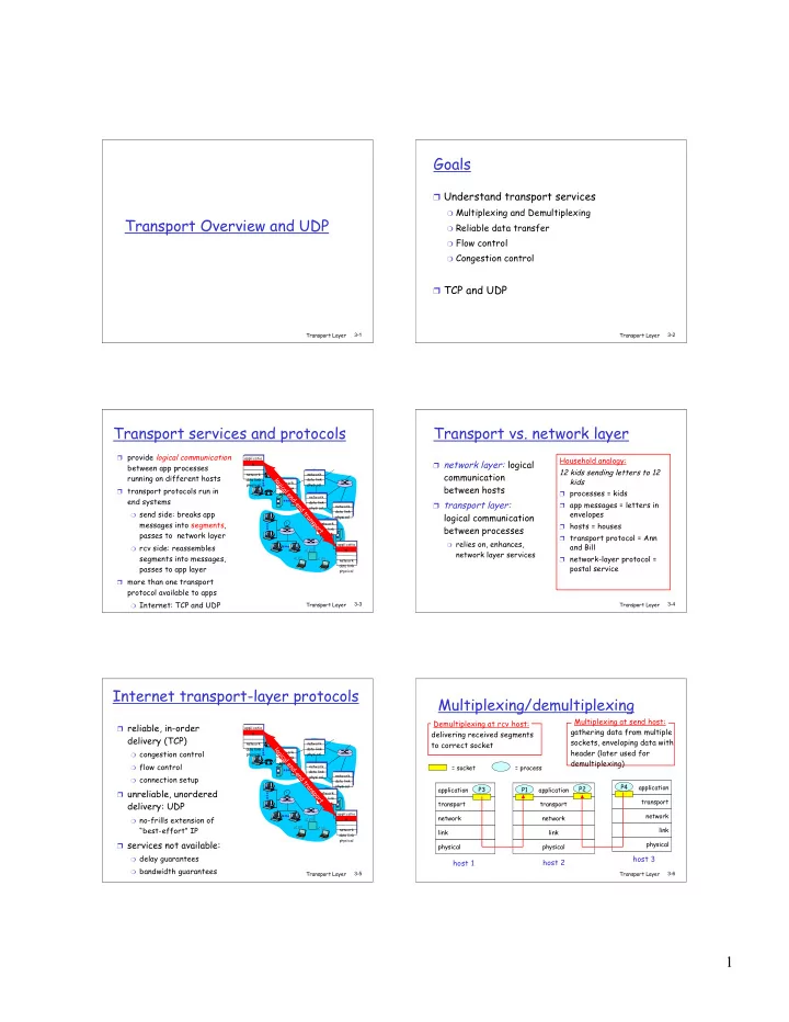
Multiplexing/demultiplexing

application transport network link physical P1 application transport network link physical application transport network link physical P2 P3 P4 P1

host 1 host 2 host 3

= process = socket

delivering received segments to correct socket Demultiplexing at rcv host: gathering data from multiple sockets, enveloping data with header (later used for demultiplexing) Multiplexing at send host:

slide-2
SLIDE 2

2

Transport Layer 3-7

How demultiplexing works

❒ host receives IP datagrams

❍ each datagram has source

IP address, destination IP address

❍ each datagram carries 1

transport-layer segment

❍ each segment has source,

destination port number (recall: well-known port numbers for specific applications)

❒ host uses IP addresses &

port numbers to direct segment to appropriate socket source port # dest port # 32 bits application data (message)

  • ther header fields

TCP/UDP segment format

Transport Layer 3-8

Connectionless demultiplexing

❒ Create sockets with port

numbers:

DatagramSocket mySocket1 = new DatagramSocket(99111); DatagramSocket mySocket2 = new DatagramSocket(99222); ❒ UDP socket identified by

two-tuple: (dest IP address, dest port number)

❒ When host receives

UDP segment:

❍ checks destination port

number in segment

❍ directs UDP segment to

socket with that port number ❒ IP datagrams with

different source IP addresses and/or source port numbers directed to same socket

Transport Layer 3-9

Connectionless demux (cont)

DatagramSocket serverSocket = new DatagramSocket(6428); Client

IP:B P2

client IP: A

P1 P1 P3

server IP: C

SP: 6428 DP: 9157 SP: 9157 DP: 6428 SP: 6428 DP: 5775 SP: 5775 DP: 6428

SP provides “return address”

Transport Layer 3-10

Connection-oriented demux

❒ TCP socket identified

by 4-tuple:

❍ source IP address ❍ source port number ❍ dest IP address ❍ dest port number

❒ recv host uses all four

values to direct segment to appropriate socket

❒ Server host may

support many simultaneous TCP sockets:

❍ each socket identified by

its own 4-tuple ❒ Web servers have

different sockets for each connecting client

❍ non-persistent HTTP will

have different socket for each request

Transport Layer 3-11

Connection-oriented demux (cont)

Client

IP:B P1

client IP: A

P1 P2 P4

server IP: C

SP: 9157 DP: 80 SP: 9157 DP: 80 P5 P6 P3 D-IP:C S-IP: A D-IP:C S-IP: B SP: 5775 DP: 80 D-IP:C S-IP: B

Transport Layer 3-12

Connection-oriented demux: Threaded Web Server

Client

IP:B P1

client IP: A

P1 P2

server IP: C

SP: 9157 DP: 80 SP: 9157 DP: 80 P4 P3 D-IP:C S-IP: A D-IP:C S-IP: B SP: 5775 DP: 80 D-IP:C S-IP: B

slide-3
SLIDE 3

3

Transport Layer 3-13

UDP: User Datagram Protocol [RFC 768]

“no frills,” “bare bones” Internet transport protocol

“best effort” service, UDP segments may be:

❍ lost ❍ delivered out of order to

app

connectionless:

❍ no handshaking between

UDP sender, receiver

❍ each UDP segment

handled independently of

  • thers

Transport Layer 3-14

UDP: more

❒ often used for streaming

multimedia apps

❍ loss tolerant ❍ rate sensitive

❒ other UDP uses

❍ DNS ❍ SNMP

❒ reliable transfer over

UDP: add reliability at application layer

❍ application-specific

error recovery! source port # dest port # 32 bits Application data (message) UDP segment format length checksum Length, in bytes of UDP segment, including header

Transport Layer 3-15

UDP checksum

Sender:

❒ treat segment contents

as sequence of 16-bit integers

❒ checksum: addition (1’s

complement sum) of segment contents

❒ sender puts checksum

value into UDP checksum field

Receiver:

❒ compute checksum of

received segment

❒ check if computed checksum

equals checksum field value:

❍ NO - error detected ❍ YES - no error detected.

But maybe errors nonetheless? More later ….

Goal: detect “errors” (e.g., flipped bits) in transmitted segment

Transport Layer 3-16

Internet Checksum Example

❒ Note ❍ When adding numbers, a carryout from the

most significant bit needs to be added to the result

❒ Example: add two 16-bit integers 1 1 1 1 0 0 1 1 0 0 1 1 0 0 1 1 0 1 1 1 0 1 0 1 0 1 0 1 0 1 0 1 0 1 1 1 0 1 1 1 0 1 1 1 0 1 1 1 0 1 1 1 1 0 1 1 1 0 1 1 1 0 1 1 1 1 0 0 1 0 1 0 0 0 1 0 0 0 1 0 0 0 0 1 1 wraparound sum checksum