
SLIDE 1
1
William Stallings Data and Computer Communications 7th Edition
Chapter 8 Multiplexing
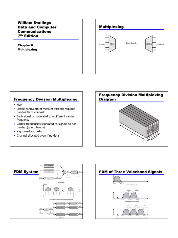
Multiplexing Frequency Division Multiplexing
- FDM
- Useful bandwidth of medium exceeds required
bandwidth of channel
- Each signal is modulated to a different carrier
frequency
- Carrier frequencies separated so signals do not
- verlap (guard bands)
- e.g. broadcast radio
- Channel allocated even if no data