1 IEEE 802.15.4 PHY IEEE 802.15.4 PHY Features Receiver Energy - - PDF document

1
SMART_READER_LITE
LIVE PREVIEW

1 IEEE 802.15.4 PHY IEEE 802.15.4 PHY Features Receiver Energy - - PDF document

Structure of Presentation Introduction 8 0 2.15.4 and Zigbee IEEE 812.15.4 WPAN IEEE 802.15.4 PHY IEEE 802.15.4 MAC Zigbee Routing Layer Kevin Klues Department of Computer Science and Engineering 2 Introduction Zigbee and


slide-1
SLIDE 1

1

8 0 2.15.4 and Zigbee

Kevin Klues

Department of Computer Science and Engineering

2

Structure of Presentation

Introduction IEEE 812.15.4 WPAN IEEE 802.15.4 PHY IEEE 802.15.4 MAC Zigbee Routing Layer

3

Introduction

Wired telephony network Cellular Network

  • Need for mobility
  • Cost of laying new wires

Cellular Network WLAN

  • IEEE 802.11
  • Long range (100m), Data throughput of 2-11Mbps

WLAN WPAN

  • Low-cost, low power, short range, very small size
  • High rate(802.15.3) – Multi-Media
  • Medium rate(802.15.1) – Cell phones, PDA, Voice
  • Low rate (802.15.4) – relaxed QoS, very low power

4

Zigbee and 802.15.4

ZigBee

  • Low data rate, low power consumption, wireless networking

protocol aimed at automation and remote control applications

802.15.4

  • Focuses on specification of lower 2 layers of protocol stack
  • Details specification of PHY and MAC by offering building

blocks for “star, mesh, and cluster tree networks”

ZigBee vs. Bluetooth

  • Simpler, lower data rate, sleeps more often
  • Leads to longer lifetimes, but less responsive

5

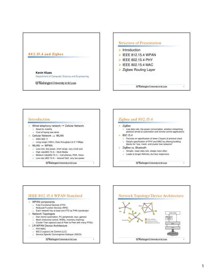
IEEE 802.15.4 WPAN Standard

WPAN components

  • Fully Functional Devices (FFD)
  • Reduced Function Devices (RFD)
  • Each network has at least one FFD as PAN coordinator

Network Topologies

  • Star (home automation, PC peripherals, toys, games)
  • Mesh (industrial control, WSNs, inventory tracking)
  • Cluster Tree (special case of Peer-to Peer with many FFDs)

LR-WPAN Device Architecture

  • PHY/MAC
  • 802.2 Logical Link Control (LLC)
  • Service Specific Convergence Sublayer (SSCS)

6

Network Topology/ Device Architecture

slide-2
SLIDE 2

2

7

IEEE 802.15.4 PHY

Features

  • Activation/Deactivation of radio transceiver
  • Energy Detection (ED)
  • Link Quality Indication (LQI)
  • Channel Selection
  • Clear Channel Assessment (CCA)
  • Transmission/Reception of packets over physical medium

8

IEEE 802.15.4 PHY

Receiver Energy Detection

  • Estimate of received signal power within bandwidth of

channel

  • Intended for use by network layer for channel selection

Link Quality Indication

  • Characterization of strength /quality of received packet
  • Implemented using ED, SNR, or combination

Clear Channel Assessment

  • Energy above ED threshold
  • Carrier Sense Only
  • Carrier Sense with energy above threshold

9

IEEE 802.15.4 PHY

PHY protocol data unit

  • SHR – allows receiving device to synchronize with bit stream
  • PHR – contains frame length information
  • Variable length payload carriying MAC sublayer frame

10

IEEE 802.15.4 MAC

Features

  • Beacon Management
  • Channel Access
  • Guaranteed Time Slot (GTS ) management
  • Frame Validation
  • Acknowledged Frame Delivery
  • Association/Dissassociation with PAN coordinator

11

IEEE 802.15.4 MAC

Superframe Structure

  • Format defined by coordinator
  • Bounded by network beacons
  • Divided into 16 equally sized slots

12

IEEE 802.15.4 MAC

Superframe Structure

  • Contention Access Period (CAP) – CSMA-CA
  • Contention Free Period (CFP) – GTS
  • Can allocate up to 7 GTSs, each longer than 1 time slot
slide-3
SLIDE 3

3

13

IEEE 802.15.4 MAC

Details

  • Beacons transmitted at start of slot 0 without CSMA
  • CAP starts immediately after Beacon
  • CFP starts on slot boundary immediately following CAP
  • CFP extends to end of active period
  • Devices can sleep during inactive period until next beacon
  • PANs not wishing to use Superframe structure always use

unslotted CSMA-CA to access channel and are always active

14

Data Transfer Model

Three types of data transfer

Coordinator to Device Device to Coordinator Between peer devices

15

Data Transfer Model

Beacon Enabled Mode Non-Beacon Enabled Mode Coordinator to Device Device to Coordinator

16

Data Transfer Model

Coordinator to Device (Beacon-Enabled)

  • Coordinator indicates in beacon message that data pending
  • Device requests data using slotted CSMA-CA
  • Coordinator acknowledges request
  • Data sent from coordinator to device
  • Device acknowledges data sent

17

Data Transfer Model

Coordinator to Device (NonBeacon-Enabled)

  • Coordinator stores pending data and waits for request
  • Device requests data using unslotted CSMA-CA at

application-defined rate

  • Coordinator acknowledges request
  • Data sent from coordinator to device
  • Device acknowledges data sent

18

Data Transfer Model

Device to Coordinator (Beacon-Enabled)

  • Device listens for network beacon
  • When found, synchronizes to superframe structure
  • At right time it transmits its data frame using slotted CSMA-

CA to coordinator

  • Space for optional acknowledgements at end of slot
slide-4
SLIDE 4

4

19

Data Transfer Model

Device to Coordinator (NonBeacon-Enabled)

  • Simply transmits data frame using unslotted CSMA-CA

20

Data Transfer Model

Peer to Peer (NonBeacon-Enabled)

  • Any device communicates with any other within its

transmission radius

  • Asynchronous – always on, use CSMA-CA
  • Synchronous – duty cycle to save power, still use CSMA-CA

21

Association/ Disassociation with PAN

Devices scan channel to find PANs within range List of available PANs for association generated How to choose a suitable PAN with which to associate is up to the APPLICATION

22

Association/ Disassociation with PAN

Coordinator decides to release device from PAN

  • Sends disassociation notification command to device
  • Device sends ack that it has disassociated itself

Device decides to release itself from PAN

  • Sends disassociaton notification command to coordinator
  • Coordinator sends ack that it has disassociated device

Both devices and coordinator remove all references of each other

23

Synchronisation

Beacon-Enabled

  • Synchronisation performed by receiving and decoding

beacon frames

NonBeacon Enabled

  • Synchronisation performed by polling the coordinator for data

Orphaned Devices

  • Orphan notification commands to re-synchronise
  • Timeout before device considered orphaned

24

Transmission/ Reception/ Ack

Beacon-Enabled Transmission

  • Transmitting device finds beacon before transmission
  • If not found, uses unslotted CSMA-CA to send
  • If found, transmits in appropriate portion of superframe
  • Transmissions in CAP use CSMA, in GTS no CSMA

Beacon-Enabled Reception

  • Device determines that data for it is pending by examining

beacon message contents

  • If data pending, sends request for that data to coordinator
slide-5
SLIDE 5

5

25

MAC Frame Formats

General MAC Frame format

26

802.15.4 MAC vs. B-MAC

Both tunable in terms of duty cycling for power efficiency Both use CSMA-CA to do clear channel assessment 802.15.4 has more features to allow for GTS but requires synchronisation to do so B-MAC never needs synchronisation, but may require many more bytes to be transmitted Implementation of 802.15.4 much more sophisticated and requires much more code/memory Application dependent on which one may be more power efficent

27

Zigbee Routing Layer

Hierarchical routing strategy Uses two strategies

AODV: Ad Hoc On Demand Distance Vector Cluster-Tree algorithm from Motorola

28

Ad Hoc On Demand Distance Vector

Pure on-demand route acquisition algorithm

  • Defines path of message from source to sink
  • Node IEEE 802.15.4 WPAN s not on active path don’t

maintain routing information or exchange routing tables

Primary objectives

  • Broadcast discovery packets only when necessary
  • Distinguish between local connectivity management and

general topology management

  • Disseminate information about local connectivity changes to

neighbouring mobile nodes

29

Ad Hoc On Demand Distance Vector

Reverse and Forward path information in AODV

30

Cluster-Tree Algorithm

Protocol of logical link and network layers Forms single/multi cluster tree networks Forms self-organizing network with redundancy and self-repair capabilities Nodes select cluster heads and form clusters in a self-organized manner. Self-developed clusters then connect to each

  • ther through a designated Device (DD)
slide-6
SLIDE 6

6

31

Cluster-Tree Algorithm

Multi cluster network with DD border nodes

32

Zigbee routing vs. Mint Routing

Both interact with MAC to use link quality information to determine power efficient route Both build routing tables and examine neighboring nodes to determine best route Mint assumes single sink with simple data aggregation application Zigbee assumes 802.15.4 MAC with clustering capabilites and potentially multiple sinks For simple applications Mint may be more power effiecient, but zigbee has more features

33

Critique of 802.15.4 and Zigbee

Allows for many different types of networks to be built by proper configuration of a single implementation Could be overkill for some applications, but also could be useful if network topology needs to be changed dynamically based on introduction of new nodes to the network

34

Critique of 802.15.4 and Zigbee

Large learning curve for knowing how to use and configure 802.15.4 properly Power management gains may not be as large as for other MAC/routing schemes for limited application scenarios Basic tradeoff between learning just one standard and learning how to use multiple

  • nes effectively

35

Summary

IEEE 802.15.4 WPAN

  • Defines standard for low power, low data rate networks
  • Defines network topologies that should be supported

IEEE 802.15.4 PHY

  • Physical layer specification of standard

IEEE 802.15.4 MAC

  • MAC specification of standard

Zigbee Routing Layer

  • Routing layer on top of PHY and MAC, enabling support for

the “star, mesh, and cluster-tree” network topologies

36

References