SLIDE 2 2
Usages for From-Region visibility
Amortization:
– Visibility data valid for many frames – Utilizes coherency between frames
Web Systems:
– Stream only the visible parts of the model – Overcomes latency
iewc
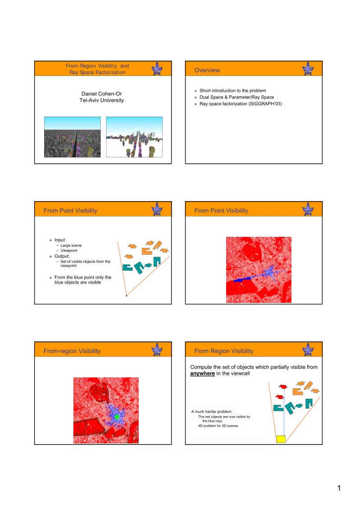
Conservative Visibility Sets
Exact Visibility Set (VS):
– Hard to compute – Superset for each individual viewpoint in the cell
PVS (Potentially Visible Set): Conservative
– Contains all the visible objects and maybe some occluded
– Easier to compute
Conservative Visibility Sets
iewcell
PVS
Conservative Visibility Sets (Cont.)
Computing a conservative PVS is the key point in designing an efficient visibility algorithm.
Tight PVS Fast computation
A top-down front-to-back
traversal.
Allows culling large parts
Simple projection and
simple image-space visibility test
Conservative
Image-space Hierarchical Computation (Cont.) Image-space Hierarchical Computation (Cont.)
Visibility test of cells is applied in every frame. Imposes overhead on rendering Using the same framework for from-region
visibility will amortize the cost over many frames!
But: we don’t have a “center of projection”
anymore – testing a cell-to cell visibility is harder.