
SLIDE 1
1 Local Cryogenics for Super-FRS SC magnets
1.1 Cryogenics for dipole stages
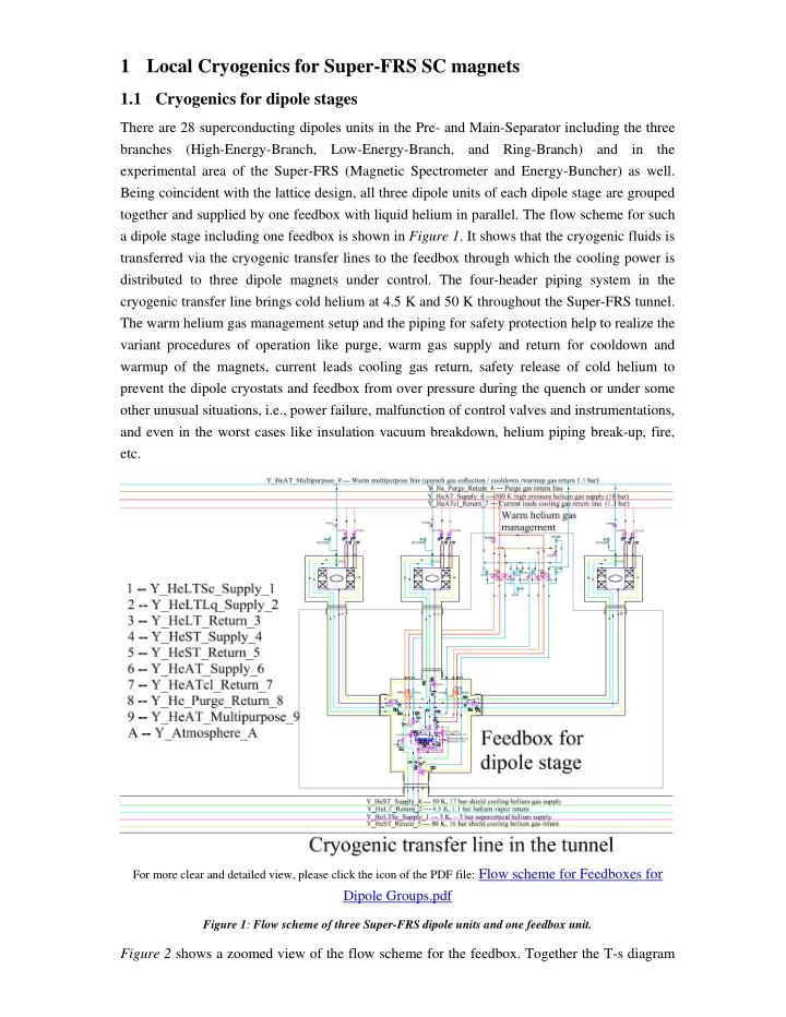
There are 28 superconducting dipoles units in the Pre- and Main-Separator including the three branches (High-Energy-Branch, Low-Energy-Branch, and Ring-Branch) and in the experimental area of the Super-FRS (Magnetic Spectrometer and Energy-Buncher) as well. Being coincident with the lattice design, all three dipole units of each dipole stage are grouped together and supplied by one feedbox with liquid helium in parallel. The flow scheme for such a dipole stage including one feedbox is shown in Figure 1. It shows that the cryogenic fluids is transferred via the cryogenic transfer lines to the feedbox through which the cooling power is distributed to three dipole magnets under control. The four-header piping system in the cryogenic transfer line brings cold helium at 4.5 K and 50 K throughout the Super-FRS tunnel. The warm helium gas management setup and the piping for safety protection help to realize the variant procedures of operation like purge, warm gas supply and return for cooldown and warmup of the magnets, current leads cooling gas return, safety release of cold helium to prevent the dipole cryostats and feedbox from over pressure during the quench or under some
- ther unusual situations, i.e., power failure, malfunction of control valves and instrumentations,