1 Interim Spent Fuel Storage Facility (ISF-2) ISF-2 - - PowerPoint PPT Presentation

1 interim spent fuel storage facility
SMART_READER_LITE
LIVE PREVIEW

1 Interim Spent Fuel Storage Facility (ISF-2) ISF-2 - - PowerPoint PPT Presentation

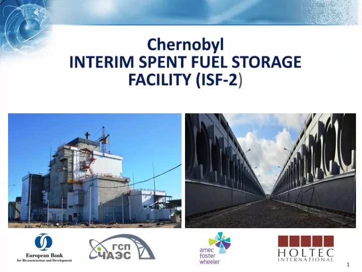
1 Interim Spent Fuel Storage Facility (ISF-2) ISF-2 Characteristics Storage of 21,297 Spent Fuel assemblies (SFA) 2,500 assemblies processed and stored per year Spent Fuel Storage Area (SFSA) includes 232 Concrete Storage Modules


slide-1
SLIDE 1

1

slide-2
SLIDE 2

2

Interim Spent Fuel Storage Facility (ISF-2)

ISF-2 Characteristics

  • Storage of 21,297 Spent Fuel assemblies (SFA)
  • 2,500 assemblies processed and stored per year
  • Spent Fuel Storage Area (SFSA) includes 232 Concrete Storage Modules

(CSM)

  • 231 Double-Walled Canisters to be supplied (DWC)
slide-3
SLIDE 3

3

ISF-1 TK-700 SFPF

SFA separation into fuel bundles Loading of fuel bundles into FT and further into DWC Drying of fuel bundles in DWC Sealing of DWC DWC transportation into SFSA

CHTS CSM

SNF Processing Chart

slide-4
SLIDE 4

4

Interim Spent Fuel Storage Facility (ISF-2)

ISF-2 is designed for processing and storage of Chernobyl RBMK reactors’ spent nuclear fuel (SNF)

SFA 8-20 mm gap 3644 3644 10054

Extension rod (ER)

Lower fuel bundle Upper fuel bundle

slide-5
SLIDE 5

5

Two main parts of the ISF-2:

Interim Spent Fuel Storage Facility (ISF-2)

  • Spent Fuel Processing

Facility

  • Spent Fuel Storage Area

SFPF (SFSA)

slide-6
SLIDE 6

6

  • Transportation - TK-700 Railcar Handling System
  • Fuel Cutting & Handling Systems
  • Fuel Tubes (FT) Handling System
  • Fuel Drying System (FGD)
  • Double-Walled Canister (DWC) Handling System

Interim Spent Fuel Storage Facility (ISF-2)

The Main Facility Processing Systems

slide-7
SLIDE 7

7

Interim Spent Fuel Storage Facility (ISF-2)

ТК-700 railcar

Fuel Transportation System:

  • Spent Fuel loaded into TK-700 railcar in existing ISF1 facility;
  • TK-700 railcar takes fuel to the ISF-2 facility for unloading into the main 'Hot

Cell' (Room 501);

Removal of Transfer Basket with SFA from TK-700 in 'Hot Cell'

slide-8
SLIDE 8

8

Interim Spent Fuel Storage Facility (ISF-2)

Fuel Assembly Cutting Machine Fuel Assembly Holder Slide Fuel Tube Double Lid System Power Manipulator

Main Fuel Process and Handling Area. Overview

Damaged Fuel Handling Table

slide-9
SLIDE 9

9

Spent Fuel handling system:

Interim Spent Fuel Storage Facility (ISF-2)

  • Removal of spent fuel from the

TK-700 & Transfer into main “Hot Cell”

  • Fuel Assembly cut into 3

sections using the cutting machine (2 fuel bundles and 1 extension rod)

  • The individual fuel bundles

placed in fuel storage tubes. SFA is attached to Holder Slide prior to cutting

  • perations

Holder Slide SFA Cutting Machine SFA

slide-10
SLIDE 10

10

Fuel assembly positioned for detachment of the Extension Rod

Upper Spent Fuel Bundle

Cutting Machine SFA (pictured during Factory Acceptance Test)

Interim Spent Fuel Storage Facility (ISF-2)

Extension rod Circular Saw of Cutting Machine

slide-11
SLIDE 11

11

Fuel Tube (FT) Handling System:

  • Receiving SFA bundles in FT’s
  • Transporting and loading of FT’s with SFA bundles inside DWC

The fuel storage tubes are made from Metamic, a neutron absorbing material; The bottom of Fuel Tube is punched to allow efficient drying of the fuel prior to final storage)

Interim Spent Fuel Storage Facility (ISF-2)

Punching and loading of FT inside DWC before drying

FT

slide-12
SLIDE 12

12

Double Walled Canister consists of three components:

  • Enclosure (double-wall) vessel
  • Internal Basket
  • Fuel Tubes (FT) 186 pcs
  • Length - 4444 mm
  • Diameter - 1876.4 mm
  • DWC empty weight - 15 704 kg
  • DWC filled weight - 31 000 kg

Interim Spent Fuel Storage Facility (ISF-2)

Enclosure vessel Internal Basket Fuel Tubes

Double Walled Canister

slide-13
SLIDE 13

13

Fuel Drying System (FGD)

  • The fuel drying system (FGD) is designed to safely remove residual water from the central

rod of the fuel bundles and to provide maximum possible removal of water that can be entrained inside fuel elements, from all SFA bundles loaded inside DWC

FGD Module Overview

Interim Spent Fuel Storage Facility (ISF-2)

slide-14
SLIDE 14

14

  • Drying SFA’s by means of FGD
  • Continuous monitoring DWC’s
  • Transporting DWC’s from SFPF
  • DWC installation in Concrete Storage

Modules (CSM)

Interim Spent Fuel Storage Facility (ISF-2)

DWC storage principle in SFSA Installation of the canisters into the concrete storage modules

DWC Concrete Storage Modules

Double Walled Canister handling system

  • Storage of empty canisters in SFPF
slide-15
SLIDE 15

15

  • The Fuel Storage area consists of 58 concrete storage modules (CSM) with 4

cells each (232 cells in total)

  • The Double Walled Canisters are to be stored in CSM for a period of 100

years.

  • The DWC’s shall be continuously monitored during the entire storage period.

DWC storage in CSM CSM DWC

Interim Spent Fuel Storage Facility (ISF-2)

slide-16
SLIDE 16

16

The analysis provided in the Design (Volume 13 “Environmental Impact Assessment”) shows that at normal operating conditions of ISF-2, the radiation effects on the objects of natural, social and anthropogenic environments will be significantly lower than the radiation, health and safety regulations (by 2-5 orders) and is acceptable from the environmental safety point

  • f view

Environmental radiation impact of ISF-2 in case of potential design-basis and beyond- design-basis accidents will not exceed radiation, health and safety regulations established by NRBU-97 for radiation accidents Project “Completion of an On-Site Dry Storage Facility (ISF-2) at Chernobyl NPP” received a positive Conclusion of the Comprehensive State Expert Review

Interim Spent Fuel Storage Facility (ISF-2)

slide-17
SLIDE 17

17

Construction and Installation works

September 2016 Pre-commissioning September 2016 Tests of equipment and systems (Cold Tests) September ÷ December 2016 Commissioning (Hot Tests) Q1 2017 Commencement of ISF-2 operation Q4 2017 Complete supply of all DWCs April 2019

Planned dates for completion of key milestones :

slide-18
SLIDE 18

18

Financing ISF-2 Construction

Nuclear Safety Account European Bank for Reconstruction and Development Administrator: European Bank for Reconstruction and Development (EBRD) Donor countries (Contributors):

France, Germany, United Kingdom, European Union, Japan, the USA, Italy, Canada, Russia, Sweden, Switzerland, Ukraine, Finland, the Netherlands, Belgium, Norway, Denmark

Interim Spent Fuel Storage Facility (ISF-2)

slide-19
SLIDE 19

19

Interim Spent Fuel Storage Facility (ISF-2)

Companies from USA, Germany, France, Italy, Belgium, Slovakia, Poland, Ukraine and other countries take part in the fabrication, supply and installation of the equipment. THE CONTINUED JOINT INTERNATIONAL SUPPORT WILL ENSURE THE COMPLETION OF THE ISF-2 FACILITY, WHICH IS IMPORTANT FOR THE SAFETY OF CHERNOBYL NPP AND BEYOND.

slide-20
SLIDE 20

20

Contract No.С2/10/062 is being implemented within the scope of Grant Agreement 006 between EBRD, Government of Ukraine and Chernobyl NPP from Nuclear Safety Account

Interim Spent Fuel Storage Facility (ISF-2)

slide-21
SLIDE 21

21

For further information the following contacts are provided:

SSE ChNPP: www.chnpp.gov.ua International Cooperation and Information Department +380 4579 26312 тел +380 4593 42175 тел/факс +380 4579 26171 тел/факс +380 4579 25746 тел

  • vm@chnpp.gov.ua

EBRD: www.ebrd.com +447741240316, +380503521106 axel.reiserer@ebrd.com, anton.usov@ebrd.com, Holtec: www.holtec.com

  • Mr. Riaz Awan,

Vice-president for International Operations/ISF- 2 Executive Sponsor, e-mail: R.Awan@holtec.com,

  • tel. +380 44 234 33 70