
SLIDE 1
In partnership with: India Institutes Fermilab Collaboration Istituto Nazionale di Fisica Nucleare Science and Technology Facilities Council
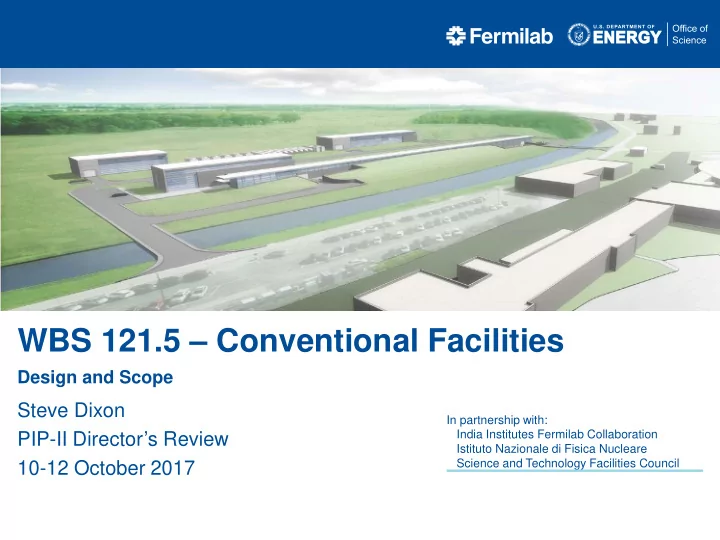
WBS 121.5 Conventional Facilities Design and Scope Steve Dixon In - - PowerPoint PPT Presentation
WBS 121.5 Conventional Facilities Design and Scope Steve Dixon In partnership with: India Institutes Fermilab Collaboration PIP-II Directors Review Istituto Nazionale di Fisica Nucleare Science and Technology Facilities Council 10-12
In partnership with: India Institutes Fermilab Collaboration Istituto Nazionale di Fisica Nucleare Science and Technology Facilities Council
10/10/17
2
10/10/17
3
10/10/17
4 Cryo Plant Building Utility Plant Building Linac Gallery Beam Transport Line Booster Connection
Work Breakdown Structure 121.5.2 Site Preparation 121.5.3 Cryo Plant Building 121.5.4 Utility Plant Building 121.5.5 High Bay Building 121.5.6 Linac Tunnel 121.5.7 Linac Gallery 121.5.8 Beam Transfer Line 121.5.9 Booster Connection
Linac Tunnel High Bay Building
10/10/17
5
Looking Southeast From Wilson Hall
AZero Service Building Tevatron Enclsoure Berm
View from Wilson Hall Looking South Along Beamline
White Flags = Warm Components Blue Flags = Cold Components
10/10/17
6 [1] – Conceptual Design Drawings can be found in PIP-II-doc-1155 [2] – Conceptual Design Report can be found at PIP-II-doc-113 [3] – Estimate Assumptions can be found at PIP-II-doc-333, Item D
10/10/17
7
10/10/17
8
WBS Identification
TeamCenter Date TeamCenter Date
121.5.2 Site Preparation
ED0006787 21-Jul-17 ED0006798 24-Jul-17
121.5.3 Cryo Plant Building
ED0006718 21-Jul-17 ED0006719 24-Jul-17
121.5.4 Utility Plant Building
ED0006748 12-Jul-17 ED0006749 7-Jul-17
121.5.5 High Bay Building
ED0006756 12-Jul-17 ED0006757 26-Jul-17
121.5.6 Linac Tunnel
ED0006790 21-Jul-17 ED0006791 21-Jul-17
121.5.7 Linac Gallery
ED0006792 21-Jul-17 ED0006793 26-Jul-17
121.5.8 Beam Transfer Line
ED0006785 20-Jul-17 ED0006786 24-Jul-17
121.5.9 Booster Connection
ED0006764 21-Jul-17 ED0006785 21-Jul-17
Functional Requirements Specification Technical Requirements Specification
10/10/17
9
10/10/17
10
Typical Technical Requirements Specification Table of Contents
10/10/17
11
Typical Technical Requirements Specification page
10/10/17
12
[4] – Meeting Minutes can be found in PIP-II-doc-70 [5] – Conceptual Design Drawings can be found in PIP-II-doc-1155 [6] – Assumptions can be found at PIP-II-doc-333 [7] – Final LSA can be found at PIP-II-doc-120
Fermilab: Alessandro Vivoli, Anindya Chakravarty, Anthony F Leveling, Arkadiy L Klebaner Beau F. Harrison, Curtis M. Baffes, David E Johnson, David W Peterson Don Cossairt, Donald V Mitchell, Emil Huedem, Jim Niehoff, Fernanda G Garcia Jerry R Leibfritz, Jerzy Czajkowski, John E Anderson Jr, Luisella Lari Matthew Quinn, Maurice Ball, Paul Derwent, Ralph J Pasquinelli Todd M Sullivan, Valeri A Lebedev, William A Pellico Consultants: Tom Lackowski, TGRWA Ron Jedziniak, LG Associates Rick Glenn, Jensen Hughes
10/10/17
13
10/10/17
14
10/10/17
15
10/10/17
16
Base Design: Eliminates this portion of the Linac Gallery (included as an Additive Alternate)
10/10/17
17
1’-10” Aisle 1’-10” Aisle RF Zone LCW Zone
10/10/17
18
Plan at Enclosure Level
FRS Section 5 (Facility Scope): The linac enclosure will be constructed with a length to accommodate two (2) HB650 cryomodules beyond the nominal compliment required for 800 MeV ~75’
10/10/17
19
(transport line and absorber)
Thanks to D. Cossairt, T. Leveling and M. Quinn
Used the 10W/m curve for the conceptual design
10/10/17
20
Cross Section Looking South at Waveguide Penetrations Cross Section Looking South at Coax Penetrations
10/10/17
21
FRS Integration and Upgradability: I2: The siting of the PIP-II facility will be consistent with future upgrades to provide 100 kW beams to the Mu2e hall on the Muon Campus
10/10/17
22
Looking Northeast Towards Booster Tower Southeast
FRS Integration and Upgradability: I4: The SC Linac will be constructed in a manner that allows installation and commissioning without interruption to ongoing accelerator
10/10/17
23
Warm Compressor Station Cold Box Station Tank Farm
10/10/17
24
10/10/17
25
Base Design Direct ICW flow through cryo compressors Base Design Cooling for pulsed mode. Additive Alternate for continuous wave cooling
10/10/17
26
Manhole P71
10/10/17
27
10/10/17
28
2014 Location
10/10/17
29
Existing Utilities and Services FRS Integration and Upgradability:
FRS Section 5 (Facility Scope):
cryomodules
10/10/17
30
8 GeV Tangent Option Northward Shift Option See PIP-II-doc-136 for Memo
10/10/17
31
10/10/17
32
Existing Data
10/10/17
33
[4] – ICW Water Quality Test Results study can be found at PIP-II-doc-155
10/10/17
34
BZero Compressor Building
Strainer
Port for Rental Strainer Port for Rental Strainer
10/10/17
35
Desription Unit Closed loop Open loop pH value 7.5 - 9.0 7.5 - 9.0 7.51 7.71 8.28 8.23 Hardness
[dH]
< 20 < 20 12.10 12.03 13.98 14.01 Carbonate hardness
[dH]
< 20 < 4 1.02 1.01 1.03 1.03 Chloride (Cl)
[mg/l]
< 100 < 100 Dissolved iron (Fe)
[mg/l]
< 0.2 < 0.2 0.07 0.07 0.10 0.12 Sulphate (SO4)
[mg/l]
< 200 < 200 36.02 34.63 46.16 44.41 Sulfide (S2-)
[mg/l]
< 0.1 < 0.1 Silicic acid (SiO2)
[mg/l]
< 200 < 200 5.62 5.56 5.52 5.54 HCO3 / SO4
> 1 Electrical conductivity
[µS/cm]
10 - 800 10 - 1500 672.00 672.00 698.00 695.00 Ammonium (NH4)
[mg/l]
< 1 < 1 0.20 0.20
Dissolved manganese (Mn)
[mg/l]
< 0.2 < 0.1 0.01 0.01 0.01 0.01 Phosphate (PO4)
[mg/l]
< 15 < 15 0.29 0.44 0.07 0.31 Glycol
[%]
20 - 40
0.00 0.00 0.00 Solids (particle size)
[mm]
< 0.1 < 0.1
Solids (particle amount)
[mg/l]
< 10 < 10 see chart see chart see chart Appearance clear, colorless clear, colorless Total bacterial count
[CFU/ml]
< 104 < 104 1,000 1,000 Proportion of non-dissolved solids
[ppm]
< 20 < 20 Algae
cells/mL
986,751 1,347,557 447 47 23,785 2,144 87 13 Magnesium
ppm
107.12 106.63 122.72 122.87 Calcium
ppm
108.86 108.13 126.81 127.12 Copper
ppm
0.00 0.00 0.00 0.00 Zinc
ppm
0.00 0.01 0.01 0.01 Sodium
ppm
62.19 61.77 60.21 59.70 Molybdate
ppm
0.01 0.00 0.00 0.01 Boron
ppm
107.12 106.63 122.72 122.87 Aluminum
ppm
0.03 0.03 0.04 0.04 Adams Strainer (75 micron) 14-Dec-16 After Before Lakos Filter (25 micron) 16-Nov-16 CUB Cooling Towers 14-Dec-17 16-Nov-16 After Before
PIP-II Requirements
21-Oct-16 Adam's Strainer (250 micron) After Before
Results:
10/10/17
36
10/10/17
37
10/10/17
38
10/10/17
39 Basis of Estimate
Pulsed Mode
LCW 1 towers HLA chilled water via CUB Cryo 1,400 gpm @17 Fdt Standby 1 tower
CW Mode
LCW 4 towers HLA (PM) chilled water via CUB HLA (CW) 2 Air Cooled Chillers Cryo 1,400 gpm @17 Fdt Standby 1 tower
10/10/17
40
10/10/17
41