Upgridding by Amalgamation: Flow-Adapted Grids for Multiscale - - PowerPoint PPT Presentation
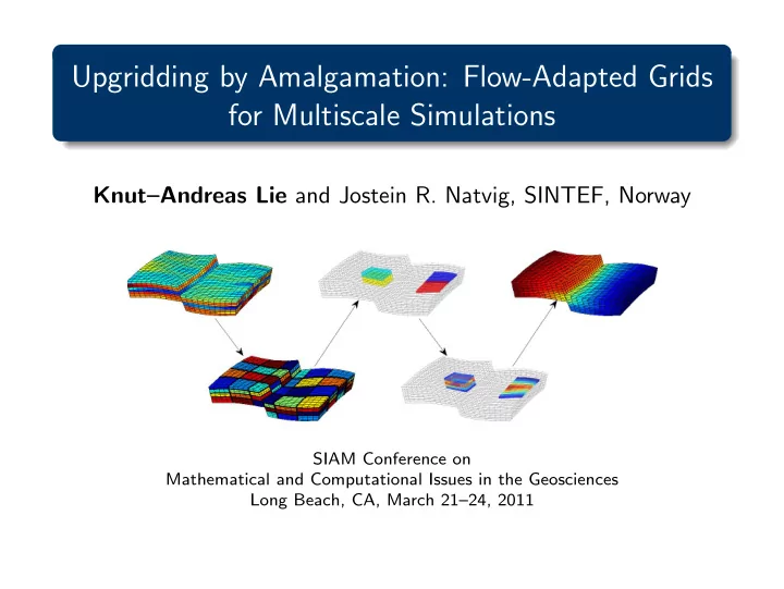
Upgridding by Amalgamation: Flow-Adapted Grids for Multiscale Simulations KnutAndreas Lie and Jostein R. Natvig, SINTEF, Norway SIAM Conference on Mathematical and Computational Issues in the Geosciences Long Beach, CA, March 2124, 2011
What is multiscale simulation?
Generally: Methods that incorporate fine-scale information into a set of coarse scale equations in a way which is consistent with the local property of the differential operator Herein: Multiscale pressure solver (upscaling + downscaling in one step)
∇ · v = q,
- v = −λ(S)K∇p
+ Transport solver (on fine, intermediate, or coarse grid)
φ∂S ∂t + ∇ “
- vf(S)
” = q
= Multiscale simulation of models with higher detail
2 / 23
What is multiscale simulation?
Coarse partitioning: Flow field with subresolution:
⇓ ⇑
Local flow problems:
⇒
Flow solutions → basis functions:
2 / 23
Flow-adapted coarse grids
Goal: Given the ability to model velocity on geomodels and transport on coarse grids: Find a suitable coarse grid that best resolves fluid transport and minimizes loss of accuracy. Formulated as the minimization of two measures:
1 the projection error between fine and coarse grid 2 the evolution error on the coarse grid 3 / 23
Flow-adapted coarsening
Assumptions:
◮ a matching polyhedral grid with n cells ci, ◮ a mapping N(c) between cell c and its nearest
neighbours,
◮ a set of flow indicators I(ci) in cell ci
ci N(ci)
We seek a coarse grid that:
◮ adapts to the flow pattern predicted by indicator I, ◮ is formed by grouping cells into N blocks Bℓ, ◮ is described by a partition vector p with n
elements, in which element pi assumes the value ℓ if cell ci is member of block Bℓ.
5 2 2 6 6 1 1 1 4 6 3 1 1 4 4 7 3 1 1 8 7 3 3 8 8
4 / 23
Coarsening principles
◮ Minimize heterogeneity of flow field inside each block min
Bj
“ X
pi=j
|I1(ci) − I1(Bj)|p |ci| ” 1
p ,
1 ≤ p ≤ ∞, ◮ Equilibrate indicator values over grid blocks min “ N X
j=1
|I2(Bj) − ¯ I2(Ω)|p |Bj| ” 1
p ,
1 ≤ p ≤ ∞, ◮ Keep block sizes within prescribed lower and upper bounds
5 / 23
Amalgamation algorithm
Amalgamation of cells:
◮ Difficult to formulate a practical and well-posed minimization problem for
- ptimal coarsening −
→ ad hoc algorithms
◮ Coarsening process steered by a set of admissible and feasible
amalgamation directions 50 × 50 lognormal permeability:
regular: 25 blocks flow magnitude: 26 blocks isocontours [p]: 26 blocks
6 / 23
Motiviation: layered reservoir
Permeability and velocity Time−of−flight Partition
7 / 23
Heuristic minimization: algorithmic components
Formulated using a set of:
sources
that create a partition vector based upon grid topology, geometry, flow-based indicator functions, error estimates, or expert knowledge supplied by the user, thereby introducing the feasible amalgamation directions
filters
that take a set of partition vectors as input and create a new partition as output, by
◮ combining/intersecting different partitions ◮ performing sanity checks, ensuring connected partitions
according to admissible directions, etc
◮ modifying partition by merging small blocks or splitting large
blocks
8 / 23
Heuristic minimization: algorithmic components
Partition:
◮ prescribed topology or predefined shapes ◮ segmentation of cells ci into bins ˜
Bℓ ci ⊂ ˜ Bℓ if I(ci) ∈ [ℓ, ℓ + 1). assuming indicator function I scaled to the interval [1, M + 1] Intersection:
◮ intersect two or more partitions to produce a new partition ◮ split multiply connected blocks into sets of singly connected cells
9 / 23
Heuristic minimization: algorithmic components
Merging: If block B violates the condition I(B) |B| ≥ NL n ¯ I(Ω) |Ω|, for a prescribed constant NL, the block is merged with the neighbouring block B′ that has the closest indicator value, i.e., B′ = argminB′′⊂N(B) |I(B) − I(B′′)|. Refinement: Refine blocks B that violate the condition I(B) |B| ≤ NU n ¯ I(Ω) |Ω|, for a prescribed constant NU
9 / 23
Example: non-uniform coarsening
Aarnes, Efendiev & Hauge (2007): Use flow velocities to make a nonuniform grid in which each coarse block admits approximately the same total flow.
log(| v|) sanity merge refine merge NUC grid
Partition: 304 blocks Merging: 29 blocks Refinement: 47 blocks Merging: 39 blocks 10 / 23
Example: non-uniform coarsening
0.1 0.2 0.3 0.4 0.5 0.6 0.7 0.8 0.9 1 0.1 0.2 0.3 0.4 0.5 0.6 0.7 0.8 0.9 1
Pore volume injected Water−cut curves
Reference solution 1648 blocks 891 blocks 469 blocks 236 blocks 121 blocks
0.1 0.2 0.3 0.4 0.5 0.6 0.7 0.8 0.9 1 0.1 0.2 0.3 0.4 0.5 0.6 0.7 0.8 0.9 1
Pore volume injected Water−cut curves
Reference solution 1581 blocks 854 blocks 450 blocks 239 blocks 119 blocks
10 / 23
Amalgamation: admissible directions (neighbourship)
Admissible directions
Topology
face neighbours edge neighbours point neighbours ...
Geometry
distance
Cell constraints
facies / rock types relperm / pc regions user supplied
Face constraints
faults horizons user supplied
11 / 23
Amalgamation: extended neighbourship (topology)
5-neighborhood 9-neighborhood
12 / 23
Amalgamation: restricted neighbourship (topology)
Upper row: N(cij) = {ci,j±1} Lower row: N(cij) = {ci,j±1, ci±1,j, ci±1,j±1}
13 / 23
Amalgamation: restricted neighbourship (facies)
Facies distribution Cartesian PEBI
Constraining to facies / saturation regions:
◮ useful to preserve heterogeneity ◮ useful to avoid upscaling kr and pc curves
13 / 23
Amalgamation: restricted neighbourship (satnum)
saturation regions regions separated region # 3 region #6
Realization from SAIGUP study, coarsening within six different saturation regions
13 / 23
Amalgamation: restricted neighbourship (faults)
5 × 5 partition 6 × 5 partition water-cut curves unconstrained 46 blocks 52 blocks
0.2 0.4 0.6 0.8 1 −0.1 0.1 0.2 0.3 0.4 0.5 0.6 0.7 0.8 0.9 Time in PVI Water fractional flow Fine grid 5x5−based coarse grid 6x5−based coarse grid
constrained 52 blocks 58 blocks
0.2 0.4 0.6 0.8 1 −0.1 0.1 0.2 0.3 0.4 0.5 0.6 0.7 0.8 0.9 Time in PVI Water fractional flow Fine grid 5x5−based coarse grid with barrier 6x5−based coarse grid with barrier
13 / 23
Amalgamation: feasible directions (indicators)
Feasible directions
Cell
error estimates
a posteriori a priori sensitivity ...
ad hoc flow-based
time of flight velocity vorticity gradients ...
a priori
permeability porosity volume ...
Face
flux velocity transmissi- bilities multipliers ...
14 / 23
Example: flow-based indicators
reference solution time-of-flight grid METIS grid 11 864 cells 127 blocks 175 blocks General observations: ◮ Time-of-flight is typically a better indicator than velocity ◮ Velocity is a better indicator than vorticity ◮ Vorticity is a better indicator than permeability ◮ . . . However, for smooth heterogeneities, the indicators tend to overestimate the importance of flow.
15 / 23
Example: hybrid methods
Velocity + Cartesian partition:
n × m intersect merge refine log | v|
Time-of-flight + Cartesian partition:
n × m intersect merge refine − log(ττr)
16 / 23
Example: hybrid methods
Satnum + velocity + Cartesian:
n × m satnum intersect merge refine log | v|
16 / 23
Flow-adapted coarsening: summary
◮ Developed a general and flexible framework
◮ Heuristic algorithms: good rather than optimal grid ◮ Algorithmic components: partition, intersection, merging,
refinement
◮ Key concepts: flow indicator, admissible and feasible directions
◮ Systematic way of generating fit-for-purpose grids
◮ Several existing methods appear as special cases
◮ Inclusion of geological information and expert knowledge
important
◮ Facies, saturation regions, surfaces, faults, etc. ◮ Predefined shapes and topologies 17 / 23
Coarse-grid discretisation
Bi-directional fluxes (upwind on fine scale):
Sn+1
ℓ
= Sn
ℓ −
∆t φℓ|Bℓ| h f(Sn+1
ℓ
) X
∂Bℓ
max(vij, 0) − X
k=ℓ
“ f(Sn+1
k
) X
Γkℓ
min(vij, 0) ”i .
This gives a centred scheme on the coarse scale Net fluxes:
Sn+1
ℓ
= Sn
ℓ −
∆t φℓ|Bℓ| X
k=ℓ
max “ f(Sn+1
ℓ
) X
Γkℓ
vij, −f(Sn+1
k
) X
Γkℓ
vij ” .
This gives an upwind scheme on the coarse scale
18 / 23
Coarse-grid discretisation: numerical diffusion
reference net fluxes bi-directional fluxes Layer 37 from SPE10
19 / 23
Coarse-grid discretisation: matrix structure
Flow-adapted grid Cartesian grid
50 100 20 40 60 80 100 120 nz = 721 50 100 20 40 60 80 100 120 nz = 484 50 100 150 20 40 60 80 100 120 140 160 nz = 585 50 100 150 20 40 60 80 100 120 140 160 nz = 452
Layer 68 from SPE10. Top: bi-directional fluxes. Bottom: net fluxes
20 / 23
Coarse-grid discretisation: numerical errors
Tarbert
fine coarse water cut 0.05 0.1 0.15 0.2 0.25 NUC/Cart − bidir NUC/Cart − upw NUC − bidir NUC − upw Cart − bidir Cart − upw
Average errors over all layers of the two formations in SPE10
21 / 23
Coarse-grid discretisation: numerical errors
Upper Ness
fine coarse water cut 0.05 0.1 0.15 0.2 0.25 NUC/Cart − bidir NUC/Cart − upw NUC − bidir NUC − upw Cart − bidir Cart − upw
Average errors over all layers of the two formations in SPE10
21 / 23
Dynamical adaption
◮ Inaccurate representation of strong displacement
fronts can lead to significant errors.
◮ Idea: Refine dynamically around strong fronts. ◮ For a Buckley–Leverett displacement:
◮ Unswept region ahead of the displacement:
coarse grid.
◮ Swept region behind the front: coarse grid. ◮ At the front: fine or intermediate grid.
coarse fine coarse
22 / 23
Example: layers from SPE10
After injection of 0.1 PVI adaptive coarse fine grid Layer 22 from SPE10
23 / 23
Example: layers from SPE10
After injection of 0.5 PVI adaptive coarse fine grid Layer 22 from SPE10
23 / 23
Example: layers from SPE10
0.2 0.4 0.6 0.8 1 1.2 0.1 0.2 0.3 0.4 0.5 0.6 0.7 0.8 0.9 1 Time in PVI Water fractional flow Adapted flow−based Coarse flow−based Adapted Cartesian Coarse Cartesian Fine grid 0.2 0.4 0.6 0.8 1 1.2 0.05 0.1 0.15 0.2 0.25 Time in PVI Saturation error on coarse grid Adapted flow−based Coarse flow−based Adapted Cartesian Coarse Cartesian 0.02 0.04 0.06 0.08 0.1 0.12 0.1 0.2 0.3 0.4 Time in PVI Projection saturation error Adapted flow−based Coarse flow−based Adapted Cartesian Coarse Cartesian
Layer 37 from SPE10
23 / 23