
SLIDE 1
18.1
Unit 18
Field Programmable Gate Arrays (FPGAs) Implementing Logic Functions with Memories
18.2
HARDWARE IMPLEMENTATION TARGETS
18.3
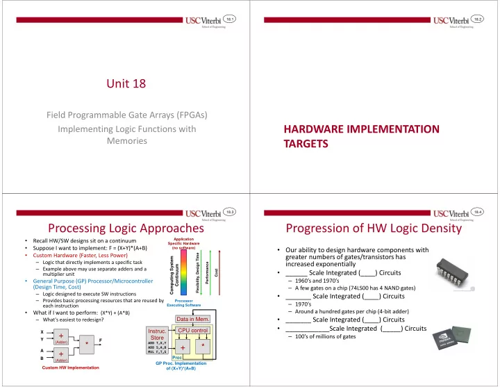
Processing Logic Approaches
- Recall HW/SW designs sit on a continuum
- Suppose I want to implement: F = (X+Y)*(A+B)
- Custom Hardware (Faster, Less Power)
– Logic that directly implements a specific task – Example above may use separate adders and a multiplier unit
- General Purpose (GP) Processor/Microcontroller
(Design Time, Cost)
– Logic designed to execute SW instructions – Provides basic processing resources that are reused by each instruction
- What if I want to perform: (X*Y) + (A*B)
– What's easiest to redesign?
+ *
CPU control Instruc. Store
ADD T,X,Y ADD S,A,B MUL F,T,S
GP Proc. Implementation
- f (X+Y)*(A+B)
+
(Adder)
+
(Adder)
*
X Y A B F Custom HW Implementation Computing System Continuum
Application Specific Hardware (no software) Processor Executing Software Flexibility, Design Time Performance Cost
Data in Mem.
Proc
18.4
Progression of HW Logic Density
- Our ability to design hardware components with
greater numbers of gates/transistors has increased exponentially
- ______ Scale Integrated (____) Circuits
– 1960’s and 1970’s – A few gates on a chip (74LS00 has 4 NAND gates)
- _______ Scale Integrated (____) Circuits
– 1970’s – Around a hundred gates per chip (4-bit adder)
- _______ Scale Integrated (____) Circuits
- ____________Scale Integrated (_____) Circuits
– 100’s of millions of gates