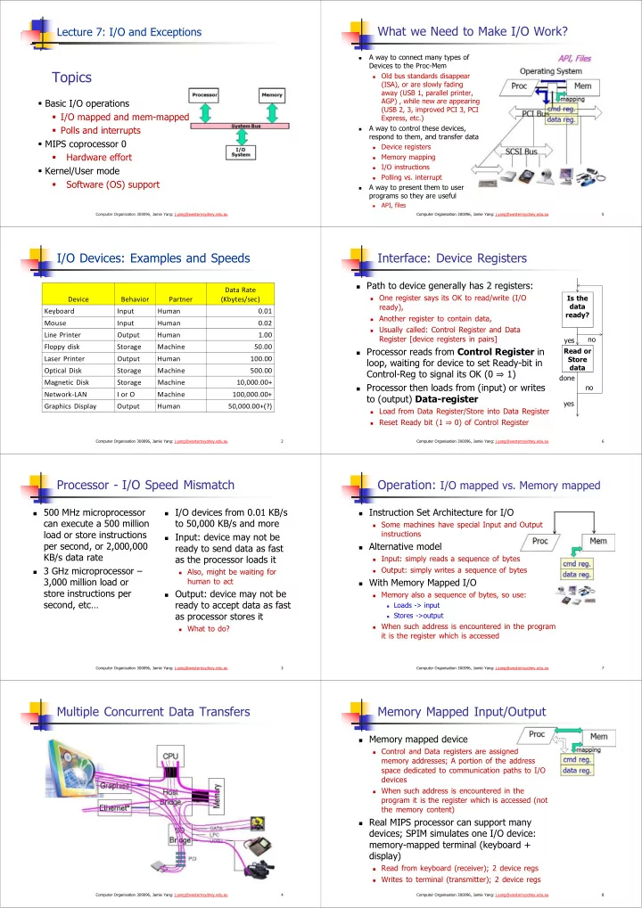
Topics Old bus standards disappear (ISA), or are slowly fading - - PDF document

topics
SMART_READER_LITE
LIVE PREVIEW

Topics Old bus standards disappear (ISA), or are slowly fading - - PDF document

What we Need to Make I/O Work? Lecture 7: I/O and Exceptions A way to connect many types of Devices to the Proc-Mem Topics Old bus standards disappear (ISA), or are slowly fading away (USB 1, parallel printer, AGP) , while new are


slide-1
SLIDE 1

Topics

  • Basic I/O operations
  • I/O mapped and mem-mapped
  • Polls and interrupts
  • MIPS coprocessor 0
  • Hardware effort
  • Kernel/User mode
  • Software (OS) support

Computer Organisation 300096, Jamie Yang: j.yang@westernsydney.edu.au

Lecture 7: I/O and Exceptions

I/O Devices: Examples and Speeds

2 Computer Organisation 300096, Jamie Yang: j.yang@westernsydney.edu.au

Device Behavior Partner Data Rate (Kbytes/sec) Keyboard Input Human 0.01 Mouse Input Human 0.02 Line Printer Output Human 1.00 Floppy disk Storage Machine 50.00 Laser Printer Output Human 100.00 Optical Disk Storage Machine 500.00 Magnetic Disk Storage Machine 10,000.00+ Network‐LAN I or O Machine 100,000.00+ Graphics Display Output Human 50,000.00+(?)

Processor - I/O Speed Mismatch

 500 MHz microprocessor

can execute a 500 million load or store instructions per second, or 2,000,000 KB/s data rate

 3 GHz microprocessor –

3,000 million load or store instructions per second, etc…

 I/O devices from 0.01 KB/s

to 50,000 KB/s and more

 Input: device may not be

ready to send data as fast as the processor loads it

 Also, might be waiting for

human to act

 Output: device may not be

ready to accept data as fast as processor stores it

 What to do? 3 Computer Organisation 300096, Jamie Yang: j.yang@westernsydney.edu.au

Multiple Concurrent Data Transfers

4 Computer Organisation 300096, Jamie Yang: j.yang@westernsydney.edu.au

What we Need to Make I/O Work?

A way to connect many types of Devices to the Proc-Mem

Old bus standards disappear (ISA), or are slowly fading away (USB 1, parallel printer, AGP) , while new are appearing (USB 2, 3, improved PCI 3, PCI Express, etc.)

A way to control these devices, respond to them, and transfer data

Device registers

Memory mapping

I/O instructions

Polling vs. interrupt

A way to present them to user programs so they are useful

API, files

5 Computer Organisation 300096, Jamie Yang: j.yang@westernsydney.edu.au

Interface: Device Registers

6 Computer Organisation 300096, Jamie Yang: j.yang@westernsydney.edu.au

Is the data ready? Read or Store data

 Path to device generally has 2 registers:

 One register says its OK to read/write (I/O

ready),

 Another register to contain data,  Usually called: Control Register and Data

Register [device registers in pairs]

 Processor reads from Control Register in

loop, waiting for device to set Ready-bit in Control-Reg to signal its OK (0 1)

 Processor then loads from (input) or writes

to (output) Data-register

 Load from Data Register/Store into Data Register  Reset Ready bit (1

0) of Control Register

yes no yes no done

Operation: I/O mapped vs. Memory mapped

 Instruction Set Architecture for I/O

 Some machines have special Input and Output

instructions

 Alternative model

 Input: simply reads a sequence of bytes  Output: simply writes a sequence of bytes

 With Memory Mapped I/O

 Memory also a sequence of bytes, so use:

 Loads -> input  Stores ->output

 When such address is encountered in the program

it is the register which is accessed

7 Computer Organisation 300096, Jamie Yang: j.yang@westernsydney.edu.au

Memory Mapped Input/Output

 Memory mapped device

 Control and Data registers are assigned

memory addresses; A portion of the address space dedicated to communication paths to I/O devices

 When such address is encountered in the

program it is the register which is accessed (not the memory content)

 Real MIPS processor can support many

devices; SPIM simulates one I/O device: memory-mapped terminal (keyboard + display)

 Read from keyboard (receiver); 2 device regs  Writes to terminal (transmitter); 2 device regs 8 Computer Organisation 300096, Jamie Yang: j.yang@westernsydney.edu.au

slide-2
SLIDE 2

Memory Mapped I/O: SPIM I/O Simulation

 Certain addresses are not regular memory  Instead: they correspond to registers in I/O devices

9 Computer Organisation 300096, Jamie Yang: j.yang@westernsydney.edu.au

Address 0 0xffffffff 0xffff0000 control reg. data reg.

Receiver Control reg mapped to 0xffff0000 Receiver Data reg mapped to 0xffff0004 Transmitter Ctrl reg mapped to 0xffff0008 Transmitter Data reg mapped to 0xffff000c

Memory Mapped I/O: SPIM I/O Simulation

 Control register rightmost bit (bit-0): Ready

 It cannot be changed by processor (just like $0)  Receiver: Ready==1 means character in Data Register arrived

but not yet been read; 1 0 when data is read from Data Register

 Transmitter: Ready==1 means transmitter is ready to accept

a new character; Transmitter still busy writing last char

 Data register rightmost byte has data

 Receiver: last char from keyboard; rest = 0  Transmitter: when rightmost byte written, writes character to

display

10 Computer Organisation 300096, Jamie Yang: j.yang@westernsydney.edu.au

Polling (or programmed I/O): Processor Checks Status before Acting

Processor reads from mapped Control Reg in loop, waiting for device to set Ready-bit in Control Reg to signal its OK (0 1)

Processor then loads from (input)

  • r writes to (output) mapped

Data Reg

 Reset Ready bit (1

0) of Control Register

Advantage:

 Simple: processor is totally in

control and does all

Disadvantage:

 Polling overhead can consume

a lot of CPU time

11 Computer Organisation 300096, Jamie Yang: j.yang@westernsydney.edu.au

busy wait loop; not an efficient way to use the CPU unless the device is very fast! checks for I/O completion can be dispersed among computation intensive code

Is the data ready? Read or Store data yes no yes no done

Implementation: I/O Polling Example

12 Computer Organisation 300096, Jamie Yang: j.yang@westernsydney.edu.au

lui $t0,0xffff # ffff0000 Waitloop1: lw $t1,0($t0) # receiver control andi $t1,$t1,0x0001 beq $t1,$zero,Waitloop1 lw $v0, 4($t0) # receiver data

 Input: Read from keyboard into $v0  Output: Write to display from $a0

lui $t0,0xffff # ffff0000 Waitloop2: lw $t1,8($t0) # transmitter control andi $t1,$t1,0x0001 beq $t1,$zero,Waitloop2 sw $a0, 12($t0) # transmitter data

 Processor waiting for I/O called “Polling”

Performance: Cost of Polling?

 Assume for a processor with a 1 GHz clock, it takes

400 clock cycles for a polling operation (call polling routine, accessing the device, and returning). Determine % of processor time for polling.

13 Computer Organisation 300096, Jamie Yang: j.yang@westernsydney.edu.au

Mouse Polled 30 times/second (polling frequency) so as not to miss user movement Floppy disk Transfers data in 2-byte units (2-bytes/poll) and has a data rate of 50 KB/second. No data transfer can be missed. Hard disk Transfers data in 16-byte chunks (16-bytes/poll) and can transfer at 16 MB/second (data rate). Again, no transfer can be missed.

% of processor time for polling

Mouse Polling

In clocks/sec : 30 [polls/sec] * 400 [clocks/poll] = 12000 clocks/sec

% Processor for polling: 12*103 (clocks/sec) / 1*109 [clocks/sec] = 0.0012%

Polling mouse little impact on processor

14 Computer Organisation 300096, Jamie Yang: j.yang@westernsydney.edu.au

Hard Disk Polling

Polling frequency (polls/sec) = 16 [MB/s] /16 [Bytes/poll] = 1M polls/sec

In clocks/sec: 1M * 400 = 400,000,000 clocks/sec

% Processor for polling: 40*107/1*109 = 40%

At 40% processor time cost? Definitely NOT acceptable!

What is the alternative to polling?

15 Computer Organisation 300096, Jamie Yang: j.yang@westernsydney.edu.au

 Wasteful to have processor spend most of its time

“spinwaiting” for I/O to be ready

 Wish we could have an unplanned (un-programmed) procedure

call that would be invoked only when I/O device is ready…

 Use exception mechanism (as in arithmetic overflow)!

 interrupt program when I/O ready,  return when done with data transfer

 An I/O interrupt is just like the exceptions except:

 More information needs to be transferred  An I/O interrupt is asynchronous with respect to instruction

execution

 It does not prevent any instruction from completion

 Pick convenient point to take an interrupt, let the current

instruction complete

Interrupt-Driven I/O

16 Computer Organisation 300096, Jamie Yang: j.yang@westernsydney.edu.au

interrupt service routine (3) Interrupt service address (1) I/O interrupt (2) Save PC (5) (4)

add sub and

  • r

read store … jr

user program Memory

slide-3
SLIDE 3

Benefit of Interrupt-Driven I/O

17 Computer Organisation 300096, Jamie Yang: j.yang@westernsydney.edu.au

 500 clock cycle overhead for each transfer, including

  • interrupt. Find the % of processor consumed if the hard

disk is only active 5% of the time.

 Interrupt rate [= Polling rate]

 Disk Interrupts/sec = 8 MB/s /16B = 500K interrupts/sec  Disk Polling Clocks/sec = 500K * 500 = 250,000,000 clocks/sec  % Processor for during transfer: 250*106/500*106= 50%

 Disk active 5%

5% * 50% 2.5% busy

Support For I/O Interrupt

18 Computer Organisation 300096, Jamie Yang: j.yang@westernsydney.edu.au

Save the PC (Program Counter) for return

 But where?

Where go when interrupt occurs?

 MIPS defines location: 0x80000180 (used to be 0x80000080)

Determine the cause of interrupt?

 MIPS has Cause Register, 4-bit field (bits 5 to 2) gives cause of

exception

Identify I/O device which caused exception?

 Convey the identity of the device generating the interrupt

How to avoid interrupts during the interrupt routine?

 What if more important interrupt occurs while servicing this

interrupt?

Who keeps track of status of all the devices, handle errors, know where to put/supply the I/O data? Hardware Instruction set OS

Hardware support For I/O Interrupt

19 Computer Organisation 300096, Jamie Yang: j.yang@westernsydney.edu.au

Portion of MIPS architecture for interrupts called “coprocessor 0”

20 Computer Organisation 300096, Jamie Yang: j.yang@westernsydney.edu.au

Portion of MIPS architecture for interrupts called “coprocessor 0”

Coprocessor 0 Registers:

Name No. Usage BadVAddr $8 Memory address (e.g. unaligned memory access) where exception occurred Status $12 Controls which interrupts are enabled Cause $13 Exception type, and pending interrupts EPC $14 PC (address of instruction) that caused exception

Coprocessor 0 Instructions

Data transfer: lwc0, swc0 [c0::reg ---- mem]

Move: (from) mfc0, (to) mtc0 [reg ---- c0::reg]

A few examples:

mfc0 $k0, $14 # $k0  c0::$14, move contents of EPC to register $k0

mtc0 $0, $13 # $0  c0::$13, clears cause register (c0::$13 gets 0).

For more see lab 10: exception handler code, and additional notes.

lwc0 $8, 0($a0)

Instruction Set Support for I/O Interrupt [Coprocessor 0 Interface] OS Support For I/O Interrupt

21 Computer Organisation 300096, Jamie Yang: j.yang@westernsydney.edu.au

OS - I/O Communication Requirements

 The OS must be able to prevent:

 The user program from communicating with the I/O device

directly, rather through controller interface

 If user programs could perform I/O directly, no protection to

the shared I/O resources

 3 types of communication are required:

 The OS must be able to give commands to the I/O devices  The I/O device must be able to notify OS when the I/O device

has completed an operation or an error occurred

 Data must be transferred between memory and I/O device

OS Memory I/O

Handling a Single Interrupt

22 Computer Organisation 300096, Jamie Yang: j.yang@westernsydney.edu.au

Put ExcCode into bits 2 to 5 of Cause $13 Status Register $12

(described later) KU IE KU IE

Turn off interrupts during interrupt routine

IE bit in $12 determines whether or not interrupts enabled:

 Interrupt Enable bit (IE) (0

  • ff, 1
  • n)

Prevent user program from turning off interrupts

KU bit determines whether in User mode or OS (Kernel) mode:

 Kernel/User bit (KU) (0

kernel, 1 user)

Copy PC into EPC ($14); PC is set to 0x80000180 Cause Register $13

(described later) ExcCode

Checks ExcCode in $13 and jumps to portion of interrupt handler which handles the current exception

When the interrupt is handled, call instruction eret/rfe to return.

Normal Run

23 Computer Organisation 300096, Jamie Yang: j.yang@westernsydney.edu.au

Interrupt Routine

24 Computer Organisation 300096, Jamie Yang: j.yang@westernsydney.edu.au

Hardware does all 0x0040002c interrupt routine 0x80000180

slide-4
SLIDE 4

Example Interrupt Routine

25 Computer Organisation 300096, Jamie Yang: j.yang@westernsydney.edu.au

Interrupt Routine Overview I

26 Computer Organisation 300096, Jamie Yang: j.yang@westernsydney.edu.au

Handler always at address 0x80000180 in kernel memory

 Use the .ktext 0x80000180 and .kdata directives

Must save and later restore all registers used

 $v0, $a0, $ra, Cause and EPC register  Including $at – use .set noat to suppress SPIM’s errors  Can temporarily spill registers to .kdata, or move to $k0 and $k1

(used freely); Should not use stack – may point to invalid memory

Parse exception code field from Cause register, and jal via jump table to appropriate routine based on ExpCode field in Cause (I/O interrupt, System call, Arithmetic Overflow)

 Mmaintaining a jump table

Restore saved registers; return control to the user program with eret (for MIPS32) or rfe (for MIPS-I (R2000))

 Jumps to EPC, and resets Exception level in Status

Multiple Interrupts

27 Computer Organisation 300096, Jamie Yang: j.yang@westernsydney.edu.au

Problem: what if we’re handling an Overflow interrupt and an I/O interrupt comes in?

Options:

 drop any conflicting interrupts: unrealistic, they may be

important

 simultaneously handle multiple interrupts: unrealistic, may not

be able to synchronize them

 queue them for later handling: sounds good

Problem: how to handle them in order of urgency?

Options:

 We need to categorize and prioritize interrupts - some

interrupts have higher level of priority

Prioritizing Interrupts

  • Interrupt Priority Levels in MIPS

28 Computer Organisation 300096, Jamie Yang: j.yang@westernsydney.edu.au

MIPS architecture enables 5 levels of HW priorities and 3 levels of SW priorities, from highest level to lowest level (8 IPLs):

 Bus error  …  Illegal Instruction/Address trap  High priority I/O Interrupt (fast response)  Low priority I/O Interrupt (slow response)

(these are the levels of interest now)

Interrupt Levels in MIPS also differ by applications

 It depends what the MIPS chip is inside of:  PalmPC, Sony Playstation 3, PSP, HP LaserJet printer, etc.

Status $12

MIPS Handling Prioritised Interrupts

29 Computer Organisation 300096, Jamie Yang: j.yang@westernsydney.edu.au 

Processor always executing at one IPL

Interrupt handlers and device drivers pick IPL to run at, this gives faster response for some interrupts

Crisp cases

If processor runs at lowest IPL level: any interrupt accepted

If processor runs at highest IPL level: all interrupts ignored

Soft cases

If processor runs at some IPL level: an interrupt accepted only if IE==1 and Interrupt Mask (IM) bit == 1 for its level (that no higher priority interrupts.)

If an interrupt occurs when Mask bit is off: don’t ignore, but pending. Cause register has a field - Pending Interrupts (PI) bits (bits 15:11) for each of the 5 HW interrupt levels - corresponding bit becomes 1 when an interrupt at its level has occurred but was not yet serviced.

Interrupt routine checks IM ANDed with PI to decide what to service next.

MIPS Handling Prioritised Interrupts

30 Computer Organisation 300096, Jamie Yang: j.yang@westernsydney.edu.au

To support interrupts of interrupts (Reentrant Interrupt Routine) , there are 3 deep stack in Status for IE,KU bits: Old (5:4) - Previous (3:2) - Current (1:0) Status Register $12

KU IE KU IE KU IE IM

O P C

Problem: When an interrupt comes in, EPC and Cause get

  • verwritten immediately by hardware. Avoid information lost?

Options: Modify interrupt handler. When next interrupt comes in:

disable interrupts (in Status Register)

save EPC, Cause, Status and Priority Level on Exception Stack

determine whether new one preempts old one

 if no, re-enable interrupts and continue with old one  if yes, may have to save state for the old one, then re-enable

interrupts, then handle new one

Interrupt Routine Overview II

31 Computer Organisation 300096, Jamie Yang: j.yang@westernsydney.edu.au

Handler always at address 0x80000180 in kernel memory

 Use the .ktext 0x80000180 and .kdata directives

Get EPC and Cause Register and Save EPC, CR, $ra

 and some general registers in memory for use in interrupt

routine

If I/O, Cause Register PI field ANDed to Status Register IM field to find unmasked interrupts (maybe several); pick the highest

Change IM of Status Register to inhibit current level and lower priority interrupts

Change Current IE of Status Register to enable interrupts

 only higher priority interrupts will get through

Jump to appropriate interrupt routine (using jump table)

On Return, restore saved registers, return control to the user program with eret / rfe

 Jumps to EPC, and resets Exception level in Status

Revision and quiz

32 Computer Organisation 300096, Jamie Yang: j.yang@westernsydney.edu.au

Device registers are a good abstraction to represent devices in memory-mapped I/O organisation: 1) True 2) False

Why I/O Polling is less efficient than I/O Interrupt?

What do the following instructions preform respectively? mfc0 $k0, $14 # mtc0 $0, $13 #

For more see lab 10: exception handler code, and additional notes.

slide-5
SLIDE 5

Recommended readings

33 Computer Organisation 300096, Jamie Yang: j.yang@westernsydney.edu.au

Text readings are listed in Teaching Schedule and Learning Guide PH4: eBook is available PH5: no eBook on library site yet PH5: companion materials (e.g.

  • nline sections for further readings)

http://booksite.elsevier.com/978012 4077263/?ISBN=9780124077263