
SLIDE 1
Topics ! Introduction ! Theory ! Transmission Media Computer - - PDF document
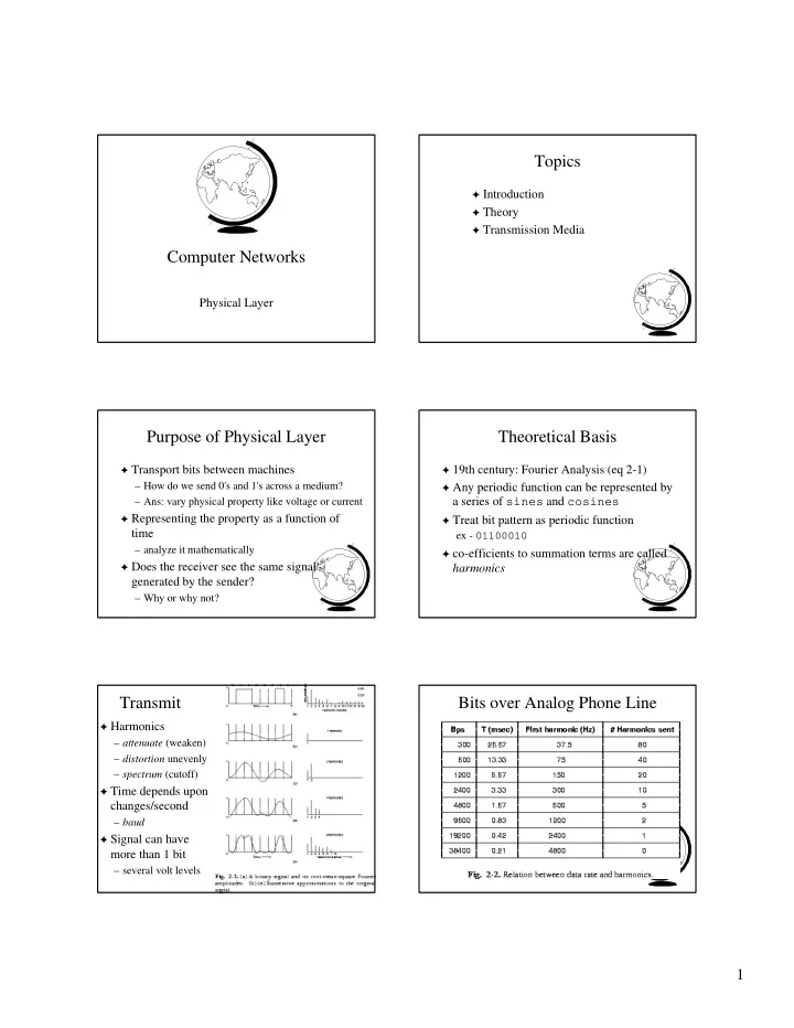
Topics ! Introduction ! Theory ! Transmission Media Computer Networks Physical Layer Purpose of Physical Layer Theoretical Basis ! Transport bits between machines ! 19th century: Fourier Analysis (eq 2-1) How do we send 0's and 1's across a
N Ex: Other conversation (faintly) on a telephone
N Ex: from lightning
N current generates a pulse of light
N training or expensive tools or parts are required
N Two fibers needed for full duplex communication
! amplitude-shift ! frequency-shift ! phase-shift modulation
! 30 degree phase shifts ! eight of frequencies
! four of frequencies
! Result: 8 + 4 * 2 = 16
! When 2400 baud :
N Manchester encoding
! No set up time ! Better channel utilization ! Less deterministic
! Billing is difficult ! Set up time ! May have quiet periods ! Known delay or capacity
! Easy to bill for a