
SLIDE 1
6/3/2016 1
Today’s Presentation
Continuous Exterior Insulation | Minnesota Building Enclosure Council | May 24, 2016 1
❸ Case Studies ❷ Design Considerations ❶ Background
1. Definitions 2. Compliance Paths 3. Historical Context 1. Thermal Bridging 2. Moisture Control 3. Drainage Plane 4. Rainscreens 1. Rainscreen Airflows 2. Convective Heat Loss 3. Insulation Gaps
Please feel free to ask questions at any point in this presentation Continuous Exterior Insulation: Design Considerations for Improved Durability and Energy Performance
- M. Steven Doggett, Ph.D., LEED AP
Built Enviornments, Inc.
Continuous Insulation
Continuous Exterior Insulation | Minnesota Building Enclosure Council | May 24, 2016 2
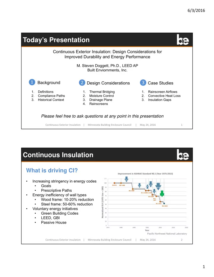
What is driving CI?
- Increasing stringency in energy codes
- Goals
- Prescriptive Paths
- Energy inefficiency of wall types
- Wood frame: 10-20% reduction
- Steel frame: 50-60% reduction
- Voluntary energy initiatives
- Green Building Codes
- LEED, GBI
- Passive House
Pacific Northwest National Laboratory