
1
TinyOS
Network Communication
Computer Network Programming Wenyuan Xu
2
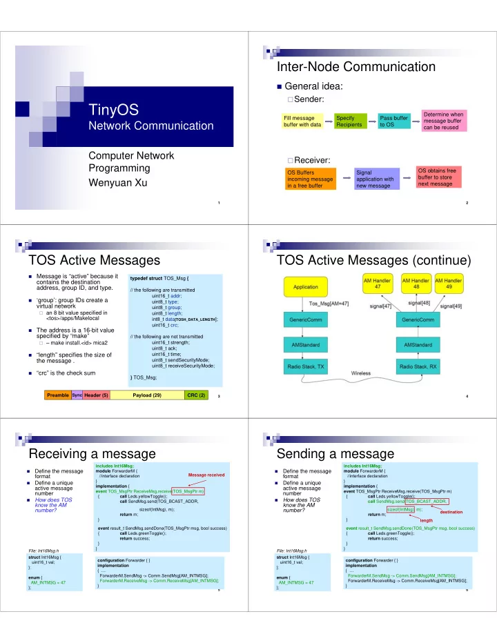
Inter-Node Communication
General idea:
Sender: Receiver:
Fill message buffer with data Specify Recipients Pass buffer to OS Determine when message buffer can be reused OS Buffers incoming message in a free buffer Signal application with new message OS obtains free buffer to store next message
3
TOS Active Messages
Message is “active” because it
contains the destination address, group ID, and type.
‘group’: group IDs create a
virtual network
an 8 bit value specified in
<tos>/apps/Makelocal
The address is a 16-bit value
specified by “make”
– make install.<id> mica2 “length” specifies the size of
the message .
“crc” is the check sum typedef struct TOS_Msg { // the following are transmitted uint16_t addr; uint8_t type; uint8_t group; uint8_t length; int8_t data[TOSH_DATA_LENGTH]; uint16_t crc; // the following are not transmitted uint16_t strength; uint8_t ack; uint16_t time; uint8_t sendSecurityMode; uint8_t receiveSecurityMode; } TOS_Msg; Preamble Header (5) Payload (29) CRC (2) Sync
4
TOS Active Messages (continue)
5
Receiving a message
- Define the message
format
- Define a unique
active message number
- How does TOS
know the AM number?
configuration Forwarder { } implementation { … ForwarderM.SendMsg -> Comm.SendMsg[AM_INTMSG]; ForwarderM.ReceiveMsg -> Comm.ReceiveMsg[AM_INTMSG]; } struct Int16Msg { uint16_t val; }; enum { AM_INTMSG = 47 }; File: Int16Msg.h includes Int16Msg; module ForwarderM { //interface declaration } implementation { event TOS_MsgPtr ReceiveMsg.receive(TOS_MsgPtr m) { call Leds.yellowToggle(); call SendMsg.send(TOS_BCAST_ADDR, sizeof(IntMsg), m); return m; } event result_t SendMsg.sendDone(TOS_MsgPtr msg, bool success) { call Leds.greenToggle(); return success; } } Message received
6
Sending a message
- Define the message
format
- Define a unique
active message number
- How does TOS
know the AM number?
configuration Forwarder { } implementation { … ForwarderM.SendMsg -> Comm.SendMsg[AM_INTMSG]; ForwarderM.ReceiveMsg -> Comm.ReceiveMsg[AM_INTMSG]; } struct Int16Msg { uint16_t val; }; enum { AM_INTMSG = 47 }; File: Int16Msg.h includes Int16Msg; module ForwarderM { //interface declaration } implementation { event TOS_MsgPtr ReceiveMsg.receive(TOS_MsgPtr m) { call Leds.yellowToggle(); call SendMsg.send(TOS_BCAST_ADDR, sizeof(IntMsg), m); return m; } event result_t SendMsg.sendDone(TOS_MsgPtr msg, bool success) { call Leds.greenToggle(); return success; } } destination length