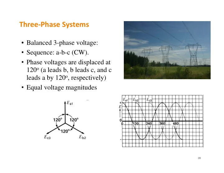
Three Phase Systems Balanced 3-phase voltage: Sequence: a-b-c - - PowerPoint PPT Presentation

three phase systems
SMART_READER_LITE
LIVE PREVIEW

Three Phase Systems Balanced 3-phase voltage: Sequence: a-b-c - - PowerPoint PPT Presentation

Three Phase Systems Balanced 3-phase voltage: Sequence: a-b-c (CW). Phase voltages are displaced at 120 o (a leads b, b leads c, and c leads a by 120 o , respectively) Equal voltage magnitudes 28 3 Phase, 4 Wire AC


slide-1
SLIDE 1

28

Three‐Phase Systems

  • Balanced 3-phase voltage:
  • Sequence: a-b-c (CW).
  • Phase voltages are displaced at

120o (a leads b, b leads c, and c leads a by 120o, respectively)

  • Equal voltage magnitudes
slide-2
SLIDE 2

29

3‐Phase, 4‐Wire AC System

Ia + Ib + Ic =Ea1/R+Eb2/R+Ec3/R =(Ea1 +Eb2 +Ec3) /R = 0

slide-3
SLIDE 3

30

3‐Phase, 3‐Wire AC System (balanced)

  • Line currents:

|Ia|=|Ib|=|Ic|= IL

  • Phase voltages (phase-to-neutral or

line-to-neutral): Nodes 1, 2, 3  Node n |Ean|=|Ebn|=|Ecn|= ELN

  • From KVL, line voltages

(line-to-line or phase-to-phase): Eab=Ean+Enb=Ean-Ebn Ebc=Ebn+Enc=Ebn-Ecn Eca=Ecn+Ena=Ecn-Ean |Eab|=|Ebc|=|Eca|= EL

EL=3 ELN  1.73 ELN ELN

slide-4
SLIDE 4

31

Wye (Y) Connection

  • Each line current (Ia, Ib and Ic) equals

the phase current. IL = IZ

  • Each line voltage is 3=1.73 times of

a phase voltage in magnitude EL=3  ELN ( |Eab|= 3 |Ean| )

  • Apparent power of each phase:
  • Total 3-phase apparent, active and reactive power:

| | 3

L Z LN Z L

E S E I I  

2 2 3

3 3 | | | | 3 | | 3

L L L L L L Y Y

S E E E I I I Z Z

 

  

3

3 cos

L L

P E I

 

3

3 sin

L L

Q E I

  | |

Y Y

Z Z   

a b c

a b c ab bc ca

 is the power factor angle and load impedance angle

slide-5
SLIDE 5

32

Delta () Connection

  • From KCL:

Ia = Iab - Ica Ib = Ibc - Iab Ic = Ica - Ibc Because three equations are symmetric, and Ia leads Ib, Ib leads Ic and Ic leads Ia all by 120o, we may easily conclude: 1. |Iab|=|Ibc|=|Ica|=IZ 2. Iab leads Ibc, Ibc leads Ica, and Ica leads Iab by 120o, respectively

  • Each line current is 3=1.73 times of a

phase current in magnitude IL=3  IZ ( |Ia|= 3 |Iab| )

  • Each phase voltage equals the line voltage

ELN = EL

a b c Iab Ibc Ica

slide-6
SLIDE 6

33

Delta () Connection

  • Apparent power of each phase:
  • Total 3-phase apparent, active and reactive power:
  • Given line voltage EL, line current IL and power factor cos, calculation of

power is independent of the connection (Y /  )

2 2 3

3 3 | | | | | 3 3 |

L L L L L L

I S E I I E E Z Z

  

   

|ZY|=|Z|/3

| | Z Z 

 

 

a b c Iab Ibc Ica

| | 3

L Z L Z L

I S E I E  

3

3 cos

L L

P E I

 

3

3 sin

L L

Q E I

 

 is the power factor angle and load impedance angle

slide-7
SLIDE 7

34

Examples 8‐8 & 8‐11

slide-8
SLIDE 8

35

Summary

  • Important questions: Exp 2-16, Prob 2-26, Exp 7-2&7-3, Prob 7-11, Exp 8-11
  • jXL=jL, jXC= -1j/(C)
  • KVL: E14=E12+E23+E34 or E41+E12+E23+E34=0
  • How many KVL & KCL are needed for N-node B-branch network?

– Keep adding new KVL and KCL equations until no new E or I can be introduced (# of KCLs: N-1; # of KVLs: B-N+1)

  • Source or Load?

1. Treat the branch with the (+) terminal receiving I as the load for calculation of power S=P+jQ 2. P>0  active load; P<0  active source; Q>0  reactive load = inductive load; Q<0  reactive source = capacitive load

  • Do calculations with all complex numbers to avoid confusion among RMS,

phasor, peak and apparent values (Saadat’s Example 2.2). – Most basic formulas S=EI* and E=IZ – Understand the power triangle for load (S=P+jQ, Z=R+jX, E leading I by )

  • Three-phase system: here to put 3