
SLIDE 1
Thermo modynami mics and ph phase transitions in ma magnetic ma materials Lec Lectur ure 2 e 2
Karl G. Sandeman ESM 2013
Outline of Lecture 2
- More on the theory of tricritical transitions
(see blackboard)
- An introduction to magnetic cooling
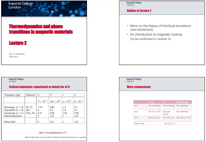
(to be continued in Lecture 3) Critical exponents: experiment vs theory for d=3
Table from Ben Simons’ lectures on Phase Transitions and Collective Phenomena, U. Cambridge.
Here “t” is proportional to T-Tc
More comparisons
Ising X-Y Heisenberg d=1 No ordering! No ordering! No ordering! d=2 β=1/8; γ=7/4 Special case! No ordering! d=3 β=0.32; γ=1 β=0.35; γ=1 β=0.36; γ=1.39 Mean field β=1/2; γ=1