The Transient Thermal Analysis at a Nuclear Containment Wall during - - PDF document

the transient thermal analysis at a nuclear containment
SMART_READER_LITE
LIVE PREVIEW

The Transient Thermal Analysis at a Nuclear Containment Wall during - - PDF document

Transactions of the Korean Nuclear Society Virtual Spring Meeting July 9-10, 2020 The Transient Thermal Analysis at a Nuclear Containment Wall during LOCA for an Analysis of a PCM Behavior Yonadan Choi, Yong Hoon Jeong Department of Nuclear


slide-1
SLIDE 1

The Transient Thermal Analysis at a Nuclear Containment Wall during LOCA for an Analysis of a PCM Behavior

Yonadan Choi, Yong Hoon Jeong  Department of Nuclear and Quantum Engineering, Korea Advanced Institute of Science and Technology, 291, Daehak-ro, Yuseong-gu, Daejeon, 34141, Republic of Korea

*Corresponding author: jeongyh@kaist.ac.kr

  • 1. Introduction

To prevent the release of a radioactive material a general nuclear power plant is equipped with multiple

  • barriers. In the case of a pressurized water reactor (PWR),

its final barrier is a thick concrete containment building. Usually, it is built to withstand even the crash of a large

  • airplane. Nevertheless, there is a possibility for a crack

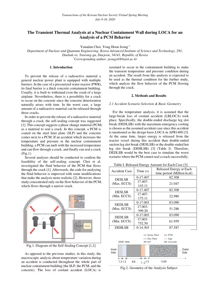
to occur on the concrete since the concrete deterioration naturally arises with time. In the worst case, a large amount of a radioactive material can be released through those cracks. In order to prevent the release of a radioactive material through a crack, the self-sealing concept was suggested [1]. This concept suggests a phase change material (PCM) as a material to seal a crack. In this concept, a PCM is coated on the steel liner plate (SLP) and the concrete comes next to a PCM. If an accident which increases the temperature and pressure in the nuclear containment building, a PCM can melt with the increased temperature and can flow through a crack, and finally can seal a crack (Fig.1). Several analyses should be conducted to confirm the feasibility of the self-sealing concept. Choi et al. investigated the fluid behavior of the PCM that flows through the crack [1]. Afterwards, the code for analyzing the fluid behavior is improved with some modifications that make the analysis more realistic [2]. However, those study concentrated only on the flow behavior of the PCM, which flows through a narrow crack. Fig.1. Diagram of the Self-Sealing Concept [1,2] As opposed to the previous studies, in this study, the macroscopic analysis about temperature variation during an accident is conducted throughout the whole part of nuclear containment building (the SLP, the PCM, and the concrete). The loss of coolant accident (LOCA) is assumed to occur in the containment building to make the transient temperature and pressure condition during an accident. The result from this analysis is expected to be used as the thermal condition for the further study, which analyze the flow behavior of the PCM flowing through the crack.

  • 2. Methods and Results

2.1 Accident Scenario Selection & Basic Geometry For the temperature analysis, it is assumed that the large-break loss of coolant accident (LBLOCA) took

  • place. Specifically, the double-ended discharge leg slot

break (DEDLSB) with the maximum emergency cooling is chosen as the assumed accident case since this accident is mentioned as the design basis LOCA in APR1400 [3]. At the same time, larger energy is released from the reactor vessel during this accident than double-ended suction leg slot break (DESLSB) or the double-ended hot leg slot break (DEHLSB) [3] (Table I). Therefore, DEDLSB would be the best case to simulate the worst scenario where the PCM cannot seal a crack successfully. Table I. Released Energy Amount for Each Case [3] Accident Case Time (s) Released Energy at Each time period (Million kcal) DESLSB (Max. ECCS) 0-17.407 82.308 17.407- 143.11 21.047 DESLSB (Min. ECCS) 0-17.407 82.308 17.407- 175.11 22.980 DEDLSB (Max. ECCS) 0-17.003 83.090 17.003- 399.20 51.286 DEDLSB (Min. ECCS) 0-17.003 83.090 17.003- 752.50 61.959 DEHLSB 0-14.303 87.587 Fig.2. Geometry of the Analysis Subject

Transactions of the Korean Nuclear Society Virtual Spring Meeting July 9-10, 2020

slide-2
SLIDE 2

The inner radius of the containment building of APR1400 starts is 21.95m [3]. The containment building

  • f APR1400 consists of two parts, the SLP, and the

concrete part. In addition, the inner side of the SLP is coated with two materials, the epoxy paint and the zinc paint, and at the same time, the gap exists between the SLP and the concrete part [3]. Besides, in this study, the PCM is coated at the outer side of the SLP. Therefore, the object for the analysis consists of 6 parts overall (Fig.2). A53 from Plusice is used in this analysis as the PCM

  • example. A PCM usually have three kinds, an organic,

inorganic (mostly salt-hydrate), and eutectic. Salt- hydrates from Plusice shows most promising properties such as a high thermal conductivity. However, an A range PCM (an organic PCM line in Plusice) is chosen since a salt-hydrate should be capsulized to be used, which is not suitable for the self-sealing. A53 has the melting point of 53℃ and latent heat of 155 kJ/kg. The

  • ther thermal properties are shown in Table II.

Density [kg/m3] Thermal Conductivity [W/m2] Specific Heat [ J kg ∙ K] Epoxy Paint 1417.6 0.277 1272.5 Zinc Paint 5462.3 1.004 891.62 SLP 7817 46.38 460.46 PCM 910 0.22 2220 Concrete 2242.6 1.59 879.06 Table II. Thermal Properties of Materials used in Simulation 2.2 Steady Condition before Accident Occur The highest temperature in the containment building during normal operation of APR1400 is 48.9℃ [3]. In addition, the highest monthly average temperature at Busan occurs on August as 29.4℃ [4]. Accordingly, it is obvious that the linear temperature condition is formed throughout the containment building at normal times. This can be easily confirmed with the simple 1D radial conduction equation and the assumption of the constant axial and tangential temperature. ℎ𝐵𝑗(𝑈

𝑏𝑗𝑠 − 𝑈 𝑗) + 𝑙𝐵𝑗+1

𝑈(𝑗 + 1) − 𝑈(𝑗) ∆𝑠 = 0 (1) 𝑙𝐵𝑗 𝑈(𝑗 − 1) − 𝑈(𝑗) ∆𝑠 + 𝑙𝐵𝑗+1 𝑈(𝑗 + 1) − 𝑈(𝑗) ∆𝑠 = 0 (2) The form of the eq. (1) applies to the boundary of the geometry, which meets the air inside and the air outside. The form of the eq. (2) applies to nodes where adjacent nodes have the same material. At nodes where two materials meet each other, thermal properties are averaged between two materials. The length between Fig.3. Steady State Temperature Distribution nodes is set to 0.1mm from epoxy paint to PCM, and set to 1mm at the concrete. The Fig. 3 shows the steady condition before accident occur. 2.3 Transient Analysis The pressure, temperature and the condensation heat transfer response during DEDLSB LOCA is shown in Fig.4, and Fig.5. Following those conditions in the containment building, the temperature variation at the containment building is calculated at each time step. The time step is set to 2.5 × 10⁻⁴ [s]. This time step makes the r-value smaller than 0.5, which is the criterion for the stable simulation while using the simple explicit scheme [5]. r = 𝛽∆𝑢 ∆𝑦 ≤ 0.5 (3) ℎ𝐵𝑗(𝑈

𝑡𝑏𝑢 − 𝑈 𝑗) + 𝑙𝐵𝑗+1

𝑈(𝑗 + 1) − 𝑈(𝑗) ∆𝑠 = 𝜍𝑑𝑊(𝑗) 𝑈(𝑗 + 1) − 𝑈(𝑗) ∆𝑢 (4) 𝑙𝐵𝑗 𝑈(𝑗 − 1) − 𝑈(𝑗) ∆𝑠 + 𝑙𝐵𝑗+1 𝑈(𝑗 + 1) − 𝑈(𝑗) ∆𝑠 = 𝜍𝑑𝑊(𝑗) 𝑈(𝑗 + 1) − 𝑈(𝑗) ∆𝑢 (5) The similar calculation with the steady case is

  • conducted. The one difference is that the transient term

is added on the right-hand side (Eq. 4,5). The another big difference is that the PCM change its phase as it is continuously heated. Therefore, the phase change term applies from the time when the temperature of the PCM reaches its melting point. 𝑙𝐵𝑗 𝑈(𝑗 − 1) − 𝑈(𝑗) ∆𝑠 + 𝑙𝐵𝑗+1 𝑈(𝑗 + 1) − 𝑈(𝑗) ∆𝑠 = 𝜍ℎ𝑔𝑕𝑊(𝑗)𝜃(𝑗) (5) As the temperature of a node of the PCM reaches its melting point, the liquid volume fraction 𝜃 starts to

Transactions of the Korean Nuclear Society Virtual Spring Meeting July 9-10, 2020

slide-3
SLIDE 3
  • increase. The temperature at the node does not change

during the phase change of that node. If 𝜃 reaches 1, the temperature at the node starts to change again since the PCM at that node has fully melted. Fig.4. Pressure and Temperature Response during Accident [3] Fig.5. Condensation Heat Transfer Coefficient Response during Accident [3] Fig.6. Transient Temperature Variation at parts near the SLP and the PCM (LPCM = 1𝑛𝑛) Fig.7. Transient Temperature Variation with Various PCM thicknesses (LPCM = 1,1.5,2𝑛𝑛) Fig.8. Transient Temperature Variation at the Concrete The temperature variation at parts near the SLP and the PCM of the 1mm thickness is shown in Fig. 6. At the same time, the temperature variations with various PCM thicknesses are shown in Fig. 7. The PCM fully melts before 100s, and the temperature of the PCM can rise more than 100℃ after large time. There were some difference of the melting time as PCM thickness changes, but the variety of the PCM thickness did not affect the

  • verall temperature trend at all.

The temperature variation at the concrete part is only shown with the case of 1mm PCM thickness since the trend is quite similar in the case of the other PCM thickness (Fig.8). The temperature change of the concrete is mostly appeared at the 1/4 inner side. The temperature of the rest part is maintained even after 1000s. From this result, the temperature variation of the PCM can be used as the initial crack inlet temperature while conducting the analysis about the crack entering liquid

  • PCM. At the same time, it is able to be assumed that the

concrete has linear temperature distribution from inside to outside since the temperature does not change much at the time when the PCM fully melted.

  • 3. Conclusions

The temperature variation at the containment building during LOCA specially DEDLSB case is calculated and presented in this study. It took from 57 to 79 s for PCM

Transactions of the Korean Nuclear Society Virtual Spring Meeting July 9-10, 2020

slide-4
SLIDE 4

to fully melt with various PCM thicknesses. The temperature of the concrete did not changed much

  • verall because the concrete is thick compared to other

part of the containment building. Therefore, at future, while conducting the other simulation to simulate the behavior of the PCM that flows through a crack, this study can provide the thermal initial condition and the varying crack inlet temperature

  • f the PCM. At the same time, the boundary wall

temperature which is the temperature of the concrete part can be assumed as it has linear distribution for the simplicity, since the temperature of the concrete part does not change much overall. ACKNOWLEDGEMENT This work was supported by KOREA HYDRO & NUCLEAR POWER CO., LTD. (No. 2018-TECH-06) REFERENCES

[1] Y. Choi, Y. H. Jeong, Feasibility Study about Self-Sealing Concept Based on the Phase Change Material (PCM) for Nuclear Containment Building, 2019 KNS spring meeting, 2019. [2] Y. Choi, D. H. Kam, Y. H. Jeong, Improvement of the Self- Sealing Simulation Code Including the Solid Layer, ANS winter meeting, Vol. 121, pp.1215-1218, 2019. [3] Shin Kori #1 & #2 Final Safety Analysis Report, Korea Hydro and Nuclear Power (KHNP). [4] 30 years’ climate average data, The meteorological administration of Korea, [5] R. H. Pletcher, D. A. Anderson, J. C. Tannehill, Computational Fluid Mechanics and Heat Transfer, CRC Press, 3rd ed., 2013. Transactions of the Korean Nuclear Society Virtual Spring Meeting July 9-10, 2020