
SLIDE 1
The Amplus Versatile Production Unit OGA/OGTC 30th Round Technology - - PowerPoint PPT Presentation
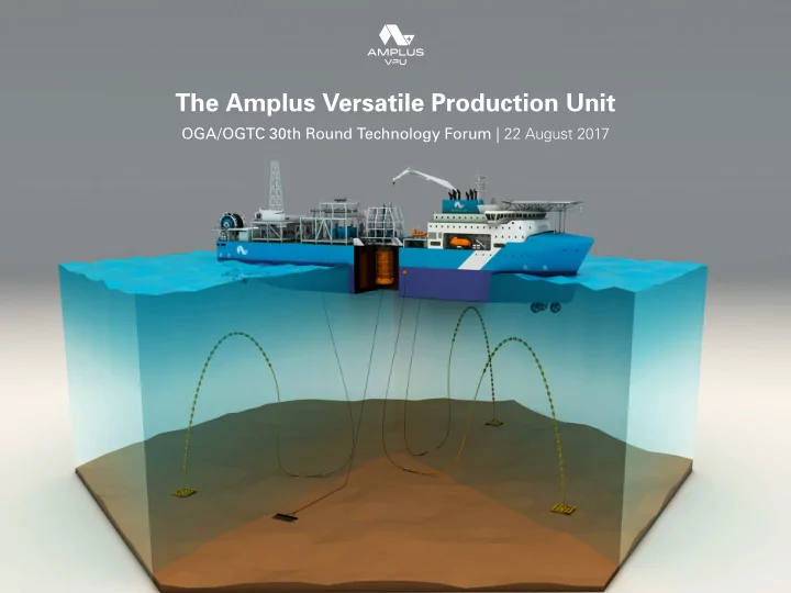
The Amplus Versatile Production Unit OGA/OGTC 30th Round Technology Forum | 22 August 2017 Contents Section 1 Overview of the Amplus VPU and the Amplus / TechnipFMC Alliance Section 2 Technical / Commercial Advantages of the Amplus VPU
2 AMPLUS VPU
3 AMPLUS VPU 3
4 AMPLUS VPU
Modular concept allows for building blocks, catering for a full range of options System designed to handle 20,000bpd. Option to increase capacity is available Produced gas to be used in engines Gas compression can be accommodated Produced water treated and discharged to sea
BASE CASE COMPONENTS Hull Turret Process
5 AMPLUS VPU
The Amplus VPU is designed to operate “Head to Weather” at all times. The VPU is so powerful, with an excess of 24 Megawatts of installed power, we can never envisage a situation of having to dis-connect for anything other than a planned event. The Modelling we have done shows that the VPU can remain on station in Hurricane Force Sea conditions and still
A recently completed study for a major oil company proved that the Amplus VPU 200 could remain connected 365 days per year in the West of Shetland area of the UKCS.
Megawatts
Days
usage
6 AMPLUS VPU
Handles a max. 20,000bpd of fluids The VPU can be equipped to support gas compression / gas lift / gas export / water treatment / water injection and downhole submersible pumps. Produced water discharged over the side after treatment +OI 100 A1 Floating Production & Oil Storage Vessel Produced gas treated in Wartsila Reformers and utilised for power generation and tank heating or reinjected
7 AMPLUS VPU
Standard turret designed for 6x 6 inch risers, 3x control umbilicals
8 AMPLUS VPU
FES have worked very closely over the past 10 years to develop a QCDC – a key component – with a maximum capacity which allows the system to be safely disconnected in a matter
quick release stab plates. The upper half of the QCDC is connected to a turntable structure mounted on the vessel to allow the risers / umbilicals to maintain a geostatic position whilst allowing the vessel to weathervane 360 Degrees, thus maximising operational uptime. The lower half of the QCDC is connected to a buoyancy unit (riser buoy) which disconnects to go subsea.
The current QCDC design limitations would be based on the following: Total QCDC load capacity including full pressure loads = 2000 Te Total Structural capacity excluding pressure loads = 1500Te (approx.) 6 –off 6inch NB 5000 PSI fluid flow lines 3 – off Hydro-electric disconnectable stab plates Maximum connected riser and umbilical tension = 25 Te (each).
9 AMPLUS VPU
Length: 153.5m Breadth: 26m FB: 17.7m Clear deck: 2400m @ 5t/m2 Power: 20MW + 20 MW boiler Deadweight: 17600t 6 x 2.5MW thrusters Total steel: 7620t Exhaust gas cleaning sulphur – yes Catalytic reduction NOX option Length: 192m Breadth: 32m FB: 17.7m Clear deck: 4200m @ 5t/m2 Power: 24MW + 20MW boiler Deadweight: 27000t 6 x 3.5MW thrusters Total weight: 36500t Exhaust gas cleaning sulphur – yes Total steel: 11689t Catalytic reduction NOX option Length: 215m Breadth: 40m FB: 20m Clear deck: 6400m @ 5t/m2 Power: 44MW + 30MW boiler 6 x 5.5MW thrusters Total weight: 53000t Exhaust gas cleaning sulphur – yes Catalytic reduction NOX option
10 AMPLUS VPU
11 AMPLUS VPU
Alliance covers the provision of flexible/ rigid flow lines, flexible risers, and all
a VPU field development. Re-use of the SURF/SPS Equipment as the VPU moves from Field to Field is also option.
12 AMPLUS VPU 12
13 AMPLUS VPU
VPU Conventional FPSO Conversion
Period and agreed with Shipyard before any Order placed – our shipyard is offering a 1% cap on Cost over runs during the build period, which
which may arise from donor hull/FPSO.
location with all the required deck strengthening, multi-fuel power generation, dis-connectable turret buoy built in from day 1.
to deliver cargoes around the world and don’t have the required deck strength or Power generation capacity to support the topsides processing equipment.
build schedule against a firm work scope with the shipyard
Register FPSO Class Notation: OI 100A1 Floating production, Storage and Offloading unit, North Sea Service (+ specific field), OIWS, LI, Ship-Right (RBA, FDA25, CM).
be difficult to achieve under new Classification Society Rules as they are classed as tankers.
vessel on location.
mooring systems, which are expensive to install, maintain and remove and generally require a large number of expensive offshore construction vessels to support the mooring installation/decommissioning works. There have been several high profile mooring system failures in the North Sea, which have resulted in large periods of lost production and significant costs associated with rebuilding the Fields Subsea architecture.
removes requirements for infield flowlines) as we can position the vessel directly over the Production/Drill centre
Production centre, which generally mean a minimum of 2 kilometres of in- field flowlines.
vessel is positioned directly over the Wells.
Production centre, which generally mean a minimum of 2 kilometres of in-field flowlines and for more challenging fluids such as waxy/heavy oil, this can be a major issue requiring significant expenditure on areas such as heated flowlines/bundles or chemicals to ensure the product flows properly.
14 AMPLUS VPU
VPU continued... Conventional FPSO Conversion continued...
CAPEX spend – the dis-connectable Turret Buoy on the VPU can be dis- connected in a planned manner in 3 – 4 hours allowing the option to return to port to pick up pre-fabricated Topsides processing modules at any time throughout the project
required Topsides processing equipment needs to be installed on day 1 of the project even if that equipment may not be required for 3 years.
from the producing wells – this has the effect of reducing the VPU’s fuel costs to a minimum and also for the majority of North Sea Marginal Fields will entirely remove/significantly reduce the need for flaring.
assist purposes and run on marine diesel, although some associated Gas may be used by Gas turbines on deck supporting the topsides processing equipment.
the Risers prior to the VPU arriving in the field – the VPU then pulls up the Turret buoy with the Risers already attached on arrival in the field – this is a 3 – 4 hour operation.
followed by the installation of the actual vessel and finally the Riser System – this tends to have the effect of placing the Risers on the Project “Critical Path” and as this is an extremely weather sensitive operation has in the past resulted in significant delays to first oil being achieved.
wellheads to remove meaning clients only have to deposit small amounts
cash available to invest in other opportunities.
mooring system, riser systems, flowlines, Subsea manifolds in addition to the Wells.
accordance with the Amplus corporate COMAH Policy, therefore the VPU accommodation block is sited at the bow of the ship.
block at the stern of the vessel placing them in a down-wind position to flames/smoke/Gas Clouds.
to operate successfully with a 37 man integrated marine/production crew.
labour intensive and the average crew size would be in the range of 75 – 125
thereby offering the client much more flexibility to use the vessel as a Portfolio asset.
design for their specific project.
15 AMPLUS VPU 15
16 AMPLUS VPU
Scenario 1 For the High Field A case it should be assumed that the 2 production wells and the water injection wells are 50-100m from the first well. For Field B the Mid case it should be assumed the additional 2 producers are equally 50- 100m apart from the first well. For the High case the wells should be assumed to be notionally 50-100m apart, located around the first well. Scenario 2 This would be a sensitivity case to determine the impact on the field economics assuming production from an existing producing field supplemented the volumes from the 2 off undeveloped fields. The input data for Field A and B as per Scenario 1. For this scenario assume existing producing facility is located 10km from Field A and 20km from Field B and takes production from a drill centre located 3km from Field A. The existing producing wells are supplemented by injection wells supplied with injection water from existing facility. The simplified schematic is shown in the following schematic.
HOST 5 km Field A Field B 5 km
VPU CENTRALLY LOCATED OPTION 1 Mobile production, VPU moves field to field, reusable subsea facilities, flowline and control umbilical risers OPTION 2 Traditional facilities manifolds, flowlines and umbilicals OPTION 3 Extended reach drilling from VPU location
Typical CNS Environment Water depth ~110m Shuttle tanker offloading STOIIP – 81 mmboe TRV – 15 mmboe Max first year production – 18900 stb/d 3 years economic production
17 AMPLUS VPU
Assume solution provider’s facility takes production from the existing drill centre and that subsea tie-in facility (at drill centre manifold) exists to allow solution provider to hook up to production from that facility. Solution provider’s facility should have facility to provide water injection to the drill centre injection wells and gas lift to the production wells. Assume that the existing facility has potential to produce 18 mmbls of recoverable reserves
Typical development options could include directly replacing existing Host with solution provider’s facility or locating solution providers facility at an alternative location and hooking up to existing drill centre. For this scenario solution would require, oil, water injection, gas lift and power lines to the existing drill centre.
EXISTING HOST 10 km Field A Field B 10 km Existing DC 20 km
VPU CENTRALLY LOCATED OPTION 1 Mobile production, VPU moves field to field, reusable subsea facilities, flowline and control umbilical risers OPTION 2 Traditional facilities manifolds, flowlines and umbilicals to Field B OPTION 3 Extended reach drilling to Field A
Typical CNS Environment Water depth ~110m Shuttle tanker offloading TRV – 33 mmboe Max first year production – 27900 stb/d 6 years economic production
18 AMPLUS VPU
For the fields above the following number of wells are assume to achieve the P50 production:
It can be assumed that the wells are situated around the main well at the centre and are notionally 50-100m apart. 20 km Field P Field Q 13 km Field R Field S Field T 11 km 12 km
Typical CNS Environment Water depth 80-90m Shuttle tanker offloading TRV (P50) – 24mmboe Max first year production – 32000 stb/d 3 years economic production
VPU CENTRALLY LOCATED OPTION 1 Mobile production, VPU moves field to field, reusable subsea facilities, flowline and control umbilical risers OPTION 2 Traditional facilities manifolds, flowlines and umbilicals OPTION 3 Extended reach drilling from VPU location
19 AMPLUS VPU 19
20 AMPLUS VPU
Day Rate Daily $ 1 VPU Bare Boat, (average though contract term) $125,000 Total Vessel Operators Lease Rate $125,000 Operations & Maintenance 1 Offshore Personnel $35,000 2 Services $11,897 3 Welfare $331 4 Process $1,532 5 Utility Systems $2,312 6 Electrical $399 7 Telecoms $340 8 Mechanical $906 9 Safety $130 10 Lube Oil $255 11 Auxillary Power Gen (FO) $158 Total Operations & Maintenance $53,260 Logistics 1 Logistics by Air (weekly) $1,736 2 Logistics by Sea $993 3 Rescue, Recovery & ERC $9,576 4 Shorebase $1,167 Total Logistics $13,472 1 Production Chemicals $4,271 Total Production Chemicals $4,271 Fuel Costs 1 Bunkering (30 days supply) $411 Total Fuel Costs $411 Total Direct Lifting Costs* $196,414
Amplus Projected Lifting Cost
UK Central North Sea Deployment
21 AMPLUS VPU 21
22 AMPLUS VPU