Testing Equipment for Electrofishing Testing equipment, - - PowerPoint PPT Presentation

testing equipment for electrofishing testing equipment
SMART_READER_LITE
LIVE PREVIEW

Testing Equipment for Electrofishing Testing equipment, - - PowerPoint PPT Presentation

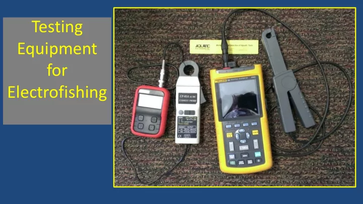
Testing Equipment for Electrofishing Testing equipment, particularly current clamps and scopemeters, have a substantial role to play in electrofishing sampling programs. Not everyone needs to be savvy in their use, but there needs to


slide-1
SLIDE 1

Testing Equipment for Electrofishing

slide-2
SLIDE 2
  • Testing equipment, particularly current clamps

and scopemeters, have a substantial role to play in electrofishing sampling programs.

  • Not everyone needs to be savvy in their use,

but there needs to be some expertise in the agency and ideally on the level of electrofishing teams.

slide-3
SLIDE 3

Outline

  • Describe purposes of testing equipment, some

approaches and considerations regarding their use, share a few of our test results, provide a list of suggested models, and demonstrate

  • peration of meters and clamp probes
slide-4
SLIDE 4

The purposes of using testing equipment include:

  • measuring voltage
  • to check control box voltage meter accuracy
  • to follow voltage standardization tables (if the gear does

not have a voltmeter)

  • to map electric fields
  • as an input to determine electrode resistance (if the gear

has no voltmeter)

slide-5
SLIDE 5

The purposes of using testing equipment include:

  • measuring current
  • to check control box amperage meter accuracy
  • to follow current standardization tables
  • to provide more accuracy than a backpack meter (that is only as

precise as the 10ths place

  • to check if anode boom electrodes are similar and functioning

properly

  • as an input to determine electrode resistance (if the gear has no

ammeter)

slide-6
SLIDE 6

The purposes of using testing equipment include:

  • measuring continuity (resistance)
  • to check that all metal surfaces are in continuity

within a boat (including proper “ground” connections between the generator and control box and the hull)

  • to check if wiring is properly configured (when

building your own gear)

slide-7
SLIDE 7

Summary

  • If your control box has accurate peak-reading voltmeters and ammeters, you don’t

need testing meters (scopemeters, current clamps) to estimate electrode resistance or to follow voltage, current, or power standardization tables. You would still need testing meters to periodically

  • check the accuracy of the control box meters,
  • follow current goal tables if your control box ammeter is not precise enough,
  • store waveforms for an equipment maintenance record, to compare among annual check-
  • ups. Stored figures can be inserted into reports or other publications. I use the

memory/download features a fair amount, primarily for adding content to training courses. As another option, you can always take pictures of the scopemeter screen.

  • find out if both booms are functioning correctly or that the boom arrays are similar, and
  • to map electric fields.
  • Control boxes with good metering definitely simplify your work, however.
slide-8
SLIDE 8

Verification Testing

  • We are going to discuss particular models
  • today. I am not advocating any particular

model, and certainly don’t pretend that the meters shown are anywhere near a comprehensive list, but present to you some

  • verall concepts to consider.
slide-9
SLIDE 9

Definitions

  • Multimeter: provides digital readout of

voltage, amperage, and resistance.

  • Scopemeter: has multimeter functions

(digital readout) and oscilloscope functions (graphical depiction of waveform)

slide-10
SLIDE 10

Definitions

  • Current Clamp (probe): when attached to a

multimeter or scopemeter, allows measurement of current without breaking into the circuit;

  • a clamp-meter has a built-in ammeter.
slide-11
SLIDE 11

Verification Testing

  • We have done a good amount of lab and field testing on

the Velleman HPS140I and the Uni-T UT81B scopemeters, by comparing to the Fluke 124 Scopemeter.

  • We also have tested the CP-05A current probe vs. the Fluke

80i-110s current clamp. These alternate equipment types compare extremely well, so the Fluke models are not the

  • nly choice for accuracy. We do not know how well the

Velleman, Uni-T or CP-05A units hold up, how long they

  • last. I have had a Fluke 124 and 80i-110s current clamp for

several years.

slide-12
SLIDE 12

Verification Testing

In addition,

  • We have compared a GTC CM600 clamp-meter

with a Fluke current clamp and oscilloscope

  • There was good agreement but under certain

conditions, which means less expensive models need to be tested always against a trusted standard

  • I will show data a bit later
slide-13
SLIDE 13

Verification Testing

In addition,

  • We have compared a peak-voltage reading multimeter

model (Fluke 87-V) with the Fluke 124 scopemeter

  • The Fluke 87-V agreed well with the Fluke 124 scopemeter unless

the waveform is very slanted and spiked. That’s the issue with multimeters- you do not see a graphic of the electrical waveform and you can’t be sure where on a slanted top waveform the peak reading is taken.

  • A number of scopemeter models are less expensive and provide a

graphic so that you have control over where you take the peak reading; thus, we recommend always going with a scopemeter

  • ver a peak-reading multimeter.
slide-14
SLIDE 14

A Bit About Scopemeters

  • First, pay strict attention to the maximum voltage input ratings to make

sure they will accommodate expected voltages you wish to measure.

– Current measurements and field mapping are made in a very low voltage range, almost always less than 5 volts and often in milli-volts, so no worries there. – The high voltage consideration comes when you are measuring directly off your electrodes. – Often, both AC and DC voltage maximums are given in the

  • specifications. Remember that meter capacities for AC are given in RMS Volts,

so the AC peak voltage limit should be about 1.4 times the rated RMS voltage (e.g., 600 Vrms x 1.4 = 840 peak Volts). If the DC maximum input is not listed, then it should be approximately 1.4 times the AC Vrms maximum.

slide-15
SLIDE 15

A Bit About Scopemeters

  • Another important

consideration is whether the scopemeter has cursors (or “markers”).

slide-16
SLIDE 16

A Bit About Scopemeters

– Cursors are used to make exact voltage measurements or time duration measurements (e.g., pulse width). – I think cursors are needed for mapping electric fields (low voltage) – Cursors may not be needed for making voltage measurements between the electrodes (often 100s of volts). I’ve seen good visual estimates but if your unit has cursors, you can go either with a visual

  • r cursor-assisted estimate of peak voltage.

– Please note that scopemeters usually can have an automatic peak voltage readout. Our experience has been that these peak voltage readouts can differ a bit from the actual (cursor) readings, particularly

  • n “ragged” square waves, so go with your cursor or visually-made

readings.

slide-17
SLIDE 17

A Bit About Scopemeters

  • Screen legibility. Glare during outside use can be a problem

with some models, particularly if you are showing others the output waveforms. Jan Dean compared the Fluke 124, Velleman HPS140I and the Uni-T UT81B during inside and

  • utside conditions. Inside, all screen legibility was good,

and Jan rated them as Fluke 124>Velleman>Uni-T. In

  • utside conditions but in the shade, the legibility was

Velleman>Uni-T>Fluke. In sunny situations, Velleman>Uni- T>Fluke. Overall, the Velleman had the most legible screen in the three lighting conditions despite having the smallest screen.

slide-18
SLIDE 18

A Bit About Scopemeters

  • Finally, some scopemeters are single channel

and some are dual channel. For our work in electrofishing, single channel works fine.

slide-19
SLIDE 19

A Bit More About Multimeters (and digital displays)

  • It is a good place here to mention the drawback of multimeters for

voltage measurement.

– First, multimeters must be peak-reading, not just provide RMS

  • readout. This is because fish primarily react to peak voltage and

current, not average. – If you are using a pulsed DC waveform, you won’t get peak with a RMS-only multimeter

– If you are using an AC waveform, since most electrofishing gear

does not generate alternating current with a true symmetrical sine- wave, you will not have a conversion factor from RMS to peak AC voltage or current.

slide-20
SLIDE 20

A Bit More About Multimeters (and digital displays)

  • If you purchase a peak-reading multimeter, there are still concerns.
  • First, they cost more than RMS multimeters (a Fluke 87 V peak-reading

multimeter retails for $350 and up). That said, we have seen the Fluke 87 V digital multimeter provide excellent peak voltage readings with a nice square pulse.

  • On the other hand, we have also observed some strange and erroneous

readings, which we weren’t able to explain. The Fluke 87 V is good at capturing very short-term voltage spikes which unfortunately may have little or no significance to the fish. You can’t know what the multimeter is reporting without seeing the waveform on a scopemeter trace.

  • Take-home: having a graphical display is the best answer.
slide-21
SLIDE 21

A Bit More About Multimeters (and digital displays)

  • If you purchase a peak-reading multimeter, there are still concerns.
  • First, they cost more than RMS multimeters (a Fluke 87 V peak-reading

multimeter retails for $350 and up). That said, we have seen the Fluke 87 V digital multimeter provide excellent peak voltage readings with a nice square pulse.

  • On the other hand, we have also observed some strange and erroneous

readings, which we weren’t able to explain. The Fluke 87 V is good at capturing very short-term voltage spikes which unfortunately may have little or no significance to the fish. You can’t know what the multimeter is reporting without seeing the waveform on a scopemeter trace.

  • Take-home: having a graphical display is the best answer.
slide-22
SLIDE 22

Regarding Current Clamp-Meters

  • The same thing goes.

– Do not trust the ones that incorporate their own display meter without an evaluation. – We recommend using current clamps that combine with a scopemeter for making voltage measurements. – That said, the Columbia Fish and Wildlife Conservation Office (U.S. Fish and Wildlife Service) found excellent correspondence between the pulsed direct current peak amp readings taken by a CM600 and the control box metering of either a MLES Infinity or an ETS MBS. (But with rectangular pulses at least 2.25 ms in width).

slide-23
SLIDE 23

Regarding Current Clamp-Meters

slide-24
SLIDE 24

Regarding Current Clamp-Meters

  • Jan Dean found that the GTC CM100 gave accurate peak

amperage readings when spot-checked against backpack metering and a scopemeter.

  • Jan also notes that the CM100 measures current in very

low amounts (range 1 milliamp to 100 Amps), and as such would be preferable for using with backpack shockers. So, for checking output levels, consider a CM600 for boats and a CM100 for backpacks, as long as you are measuring rectangular waves ≥ 2.25 ms in width.

slide-25
SLIDE 25

Some Data

Note: very low voltage levels

slide-26
SLIDE 26

Some Data

Note: very low voltage levels

slide-27
SLIDE 27

Use and Budget

  • Unless you need to use the meters constantly (as if you were using them

as an external volt or amp meter to follow standardization tables), a field

  • ffice does not necessarily need their own equipment.

– For example, a field map of a particular electrode arrangement only needs to be made once unless there are changes in the electrode design or sampling environment.

  • You could develop a central clearinghouse to provide particular test

equipment when requested. Or you could buy less expensive meters for every office and then get a more expensive meter for headquarters that has more capacity and capability. The more expensive meter, as a Fluke 124, can be used to check the accuracy of the less expensive equipment

  • ver time, serve as the “standard”, and evaluate future inexpensive

models for potential use.

slide-28
SLIDE 28

Some possible model combinations to measure volts and amperage, with emphasis on less expensive alternatives

  • Field mapping:

– Velleman HPS140I scopemeter (recommended) with a homemade voltage gradient probe; other scopemeters include the Fluke 124, UNI-T UTD1025CL, UNI-T UTD1050DL, and the UNI-T UTD1025C.

slide-29
SLIDE 29

Some possible model combinations to measure volts and amperage, with emphasis on less expensive alternatives

  • Current measurements:

– Velleman HPS140I scopemeter and CP-05 current clamp (recommended). Or use a UNI-T UTD1025CL, UNI-T UTD1050DL, UNI-T UTD1025C, or Fluke 124 scopemeter with a CP-05 current clamp. – An accurate but most expensive combination is the Fluke 124 and Fluke 80i-110S current clamp. – Finally, under conditions of a clean pulsed direct current square waveform having a pulse width greater than 2.25 ms and with minimal spike, a CM600 is a low cost option.

slide-30
SLIDE 30

Some possible model combinations to measure volts and amperage, with emphasis on less expensive alternatives

  • Voltage measurements of electrodes:

– Uni-T UT81B (recommended), UNI-T UTD1025CL, UNI-T UTD1050DL, UNI-T UTD1025C, and the Fluke 124 scopemeters. – If you are looking for an inexpensive alternative to a Fluke 124, the first real option is the Uni-T UT81B. It has a high voltage capacity and a good safety rating (600V CAT III, 1000V CAT II) to protect against transient currents which shouldn’t be a concern anyway on an electrofishing boat. One drawback is that this model does not have

  • cursors. However, you can get very good visually estimating peak from

the screen and you can get confirmation by dividing the average voltage readout by the displayed duty cycle. Both Jan and I have done some comparison testing with the Uni-T UT81B, especially Jan using a Fluke 124 for a standard, and we find it accurate.

slide-31
SLIDE 31

Demonstration

  • Operating testing equipment