
SLIDE 1
STINGER Version 2.1
1
STINGER SOFTWARE FOR CALCULATION OF SHAPED CHARGE WARHEAD JET - - PowerPoint PPT Presentation
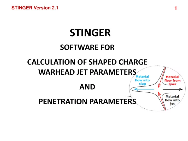
STINGER Version 2.1 1 STINGER SOFTWARE FOR CALCULATION OF SHAPED CHARGE WARHEAD JET PARAMETERS AND PENETRATION PARAMETERS STINGER Version 2.1 2 Method Combined method: Analytical based on : PER (Pugh, Eichelberger, and Rostoker)
STINGER Version 2.1
1
STINGER Version 2.1
2
STINGER Version 2.1
3
STINGER Version 2.1
4
STINGER Version 2.1
5
Detail calculation of all parameters of shape charge jet and penetration process. Analysis of the influence of various design parameters
STINGER Version 2.1
6
Caliber: 20÷200mm Charge shape: cylinder, cylinder – cone. Charge confinement: In cylindrical case Charge material: 24 predefined, plus user define possibility. Liner shape: cone and rounded apex cone with linearly
varying thickness.
Liner material: defined by density. Initiation point: defined by coordinates. Target material: Metal defined by density and Brinell
hardness
Brake up time: Automatically determined or specified.
STINGER Version 2.1
7
STINGER Version 2.1
8
STINGER Version 2.1
9
Sketch (drawing) of projectile Files and diagrams with calculated jet
Files and diagrams with calculated penetration
STINGER Version 2.1
10
STINGER Version 2.1
11
STINGER Version 2.1
12
STINGER Version 2.1
13
STINGER Version 2.1
14
STINGER Version 2.1
15
Sketch (drawing) of projectile Files and diagrams with calculated jet
Files and diagrams with calculated penetration
STINGER Version 2.1
16
STINGER Version 2.1
17
STINGER Version 2.1
18
FILE NAME DESCRIPTION Output.txt Input data and various calculated quantities. InitialPosition.txt Charge and liner characteristics vs. axial position of the cone zonal elements. CollapsePrVar.txt Data which describes collapse process of the liner MassesVelEn.txt Data about masses and velocities of the liner, jet and slug. PenetrationPhVar.txt Various parameters which describe penetration process of the jet through target. PenetrationDepth.txt Data of depth of penetration and the radius of the hole inside target corresponding with the number of zones towards liner axis. TotalPenetration.txt Values of total penetration into target in function of standoff distance between liner base and target. AlphaiAnalysis.txt Penetration parameters for different inner liner cone half angle. EPSAnalysis.txt Penetration parameters for different liner thickness at cone base.
STINGER Version 2.1
19
STINGER Version 2.1
20
STINGER Version 2.1
21
STINGER Version 2.1
22
STINGER Version 2.1
23
STINGER Version 2.1
24
STINGER Version 2.1
25
STINGER Version 2.1
26
STINGER Version 2.1
27
STINGER Version 2.1
28
STINGER Version 2.1
29
STINGER Version 2.1
30
STINGER Version 2.1
31
STINGER Version 2.1
32
STINGER Version 2.1
33
STINGER Version 2.1
34
STINGER Version 2.1
35
STINGER Version 2.1
36
STINGER Version 2.1
37
STINGER Version 2.1
38
STINGER Version 2.1
39
STINGER Version 2.1
40