
SLIDE 1
1
1
TYPES OF FORCES External Forces ≡ actions of
- ther bodies on the structure
under consideration. Internal Forces ≡ forces and couples exerted on a member
- r portion of the structure by
the rest of the structure. Inter- nal forces always occur in equal but opposite pairs.
Statics of Structural Statics of Structural Supports Supports
2
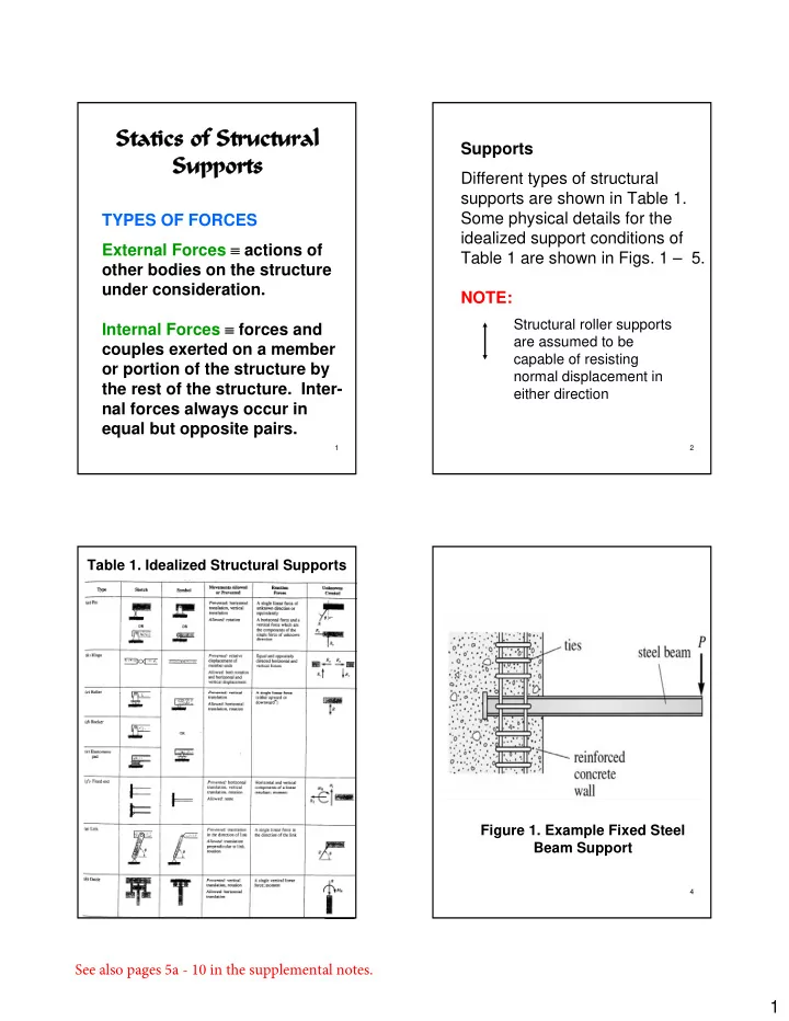
Supports Different types of structural supports are shown in Table 1. Some physical details for the idealized support conditions of Table 1 are shown in Figs. 1 – 5. NOTE:
Structural roller supports are assumed to be capable of resisting normal displacement in either direction
3
Table 1. Idealized Structural Supports
4
Figure 1. Example Fixed Steel Beam Support
See also pages 5a - 10 in the supplemental notes.