
SLIDE 1
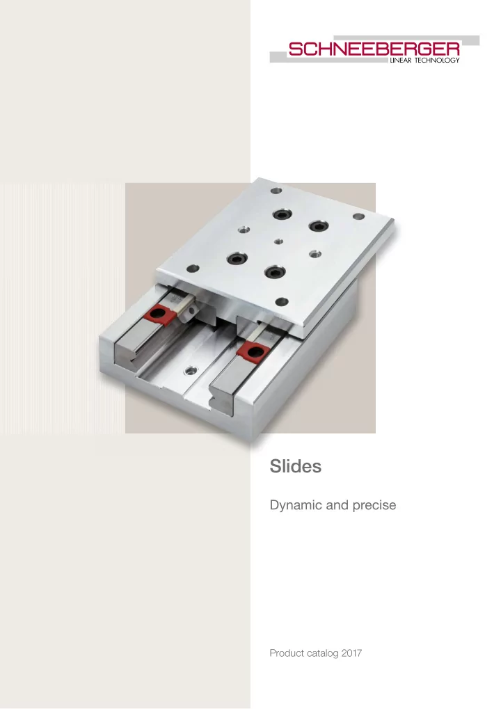
Slides Dynamic and precise Product catalog 2017 Latest version of - - PDF document
Slides Dynamic and precise Product catalog 2017 Latest version of the catalogs You can always find the latest version of our catalogs in the Download area of our website. Disclaimer This publication has been compiled with great care and all
Disclaimer This publication has been compiled with great care and all information has been checked for accuracy. However, we can assume no liability for incorrect or incomplete information. We reserve the right to make changes to the information and technical data as a result of enhancements to our products. Reprinting or reproducing, even in part, is not permitted without our written consent. Latest version of the catalogs You can always find the latest version of our catalogs in the Download area of our website.
1 Product Overview . . . . . . . . . . . . . . . . . . . . . . . . . . . . . . . . . . . . . . . . . . . . S ● 4 2 Applications 2.1 Die Attach System with ND 1 . . . . . . . . . . . . . . . . . . . . . . . . . . . . . . . . . S ● 6 2.2 Multimode Fusion Splicer with NK 1 Tables . . . . . . . . . . . . . . . . . . . . . . . S ● 7 2.3 Printed Circuit Board Assembly with NDN 1 . . . . . . . . . . . . . . . . . . . . . . S ● 8 2.4 Laser Measuring Device with ND 1 . . . . . . . . . . . . . . . . . . . . . . . . . . . . . S ● 9 3 Frictionless Tables Type NK 3.1 Frictionless Tables Type NK . . . . . . . . . . . . . . . . . . . . . . . . . . . . . . . . . S ● 11 3.2
3.3 Standard Model . . . . . . . . . . . . . . . . . . . . . . . . . . . . . . . . . . . . . . . . . . S ● 11 3.4 Special Models . . . . . . . . . . . . . . . . . . . . . . . . . . . . . . . . . . . . . . . . . . . S● 11 3.5 Specifications . . . . . . . . . . . . . . . . . . . . . . . . . . . . . . . . . . . . . . . . . . . . S● 12 3.6 Accessories . . . . . . . . . . . . . . . . . . . . . . . . . . . . . . . . . . . . . . . . . . . . . S● 16 4 Frictionless Tables Type NKL 4.1 Frictionless Tables Type NKL . . . . . . . . . . . . . . . . . . . . . . . . . . . . . . . . S ● 17 4.2
4.3 Standard Model . . . . . . . . . . . . . . . . . . . . . . . . . . . . . . . . . . . . . . . . . . S ● 17 4.4 Special Model . . . . . . . . . . . . . . . . . . . . . . . . . . . . . . . . . . . . . . . . . . . . S● 17 4.5 Specifications . . . . . . . . . . . . . . . . . . . . . . . . . . . . . . . . . . . . . . . . . . . . S● 18 5 Micro Frictionless Tables Type ND 5.1 Micro Frictionless Tables Type ND . . . . . . . . . . . . . . . . . . . . . . . . . . . . S ● 23 5.2
5.3 Standard Model . . . . . . . . . . . . . . . . . . . . . . . . . . . . . . . . . . . . . . . . . . S ● 23 5.4 Special Model . . . . . . . . . . . . . . . . . . . . . . . . . . . . . . . . . . . . . . . . . . . . S● 23 5.5 Specifications . . . . . . . . . . . . . . . . . . . . . . . . . . . . . . . . . . . . . . . . . . . . S● 24 6 Micro Frictionless Tables Type NDN 6.1 Micro Frictionless Tables Type NDN . . . . . . . . . . . . . . . . . . . . . . . . . . . S ● 27 6.2
6.3 Standard Model . . . . . . . . . . . . . . . . . . . . . . . . . . . . . . . . . . . . . . . . . . S ● 27 6.4 Specifications . . . . . . . . . . . . . . . . . . . . . . . . . . . . . . . . . . . . . . . . . . . . S● 28 7 Technical Information 7.1 Acceptance Tolerances . . . . . . . . . . . . . . . . . . . . . . . . . . . . . . . . . . . . S ● 30 7.2 Accuracy . . . . . . . . . . . . . . . . . . . . . . . . . . . . . . . . . . . . . . . . . . . . . . . S● 30 7.3 Materials . . . . . . . . . . . . . . . . . . . . . . . . . . . . . . . . . . . . . . . . . . . . . . . . S● 32 7.4 Permissible Operating Temperatures. . . . . . . . . . . . . . . . . . . . . . . . . . . S ● 32 7.5 Lubrication . . . . . . . . . . . . . . . . . . . . . . . . . . . . . . . . . . . . . . . . . . . . . . S● 32 7.6 Permissible Velocities and Accelerations . . . . . . . . . . . . . . . . . . . . . . . . S ● 32 7.7 Friction, Running Accuracy and Smoothness . . . . . . . . . . . . . . . . . . . . S ● 32 8 Design and Fitting Guidelines 8.1 Horizontal and Vertical Fitting . . . . . . . . . . . . . . . . . . . . . . . . . . . . . . . . S ● 33 8.2 Attaching Frictionless Tables. . . . . . . . . . . . . . . . . . . . . . . . . . . . . . . . . S ● 33 8.3 Preloading Frictionless Tables . . . . . . . . . . . . . . . . . . . . . . . . . . . . . . . . S ● 33 8.4 Design of Base Unit . . . . . . . . . . . . . . . . . . . . . . . . . . . . . . . . . . . . . . . S ● 33 8.5 Accessories for Frictionless Tables . . . . . . . . . . . . . . . . . . . . . . . . . . . . S ● 33 9 Dimensioning Frictionless Tables 9.1 Load Carrying Capacity and Operational Life. . . . . . . . . . . . . . . . . . . . . S ● 34 9.2 Moment Loading. . . . . . . . . . . . . . . . . . . . . . . . . . . . . . . . . . . . . . . . . . S ● 35 Table of Contents
1 Product Overview 2 Applications 5 Micro Frictionless Tables Type ND 6 Frictionless Tables Type NDN 3 Frictionless Tables Type NK 4 Frictionless Tables Type NKL 7 Technical Information 8 Design and Fitting Guidelines 9 Dimensioning Frictionless Tables
Frictionless Tables Type NK
depending on the size
to the many different sizes
with FORMULA-S
in aluminum
with FORMULA-S Frictionless Tables Type NKL
Micro Frictionless Tables Type ND Micro Frictionless Tables Type NDN
steel
helps to avoid cage creep
Product Overview
2.1 Die Attach System with ND 1 One of the ideal applications for the ND 1 table is in Die Attach equipment. Die Attach is
first step, a wafer full of IC’s is sliced up with a diamond dicing saw. After sawing, the individual IC’s or «die» are picked off of the sawed wafer and placed onto a metal lead frame in the die attach operation. The lead frame has been prepared with an epoxy adhesive, which secures the die to the leadframe. In subsequent operations, the metal pads on the die are connected to the metal leads of the frame, providing an electrical connection to the printed circuit board to which the completed IC will eventually be
and place" operation. The individual die are picked from a wafer and placed on the lead frame in a specific location. A machine vision system is used to accurately locate the independent positions of both the die on the wafer and the lead frame, where it will be
subsequent operations. Product ND 1 Stroke 25 mm Nominal stroke 15 mm Operating orientation vertical Position accuracy 0.05 mm Acceleration 30 m/s2 Straightness and Flatness of travel 0.004 mm
2.2 Multimode Fusion Splicer with NK 1 Tables Multimode Fusion Splicers are portable optical fibre joining machines weighing approxi- mately 10 kg. These are used in the field for the installation of optical fibre systems, for ex- ample for LAN’s (Local Area Networks). Using a high precision process, two optical fibres are fusion joined together. Great accuracy is required so that the transmission quality of the optical fibre is not significantly reduced. Two clamping devices, one for each fibre, accurately locate and hold the two optical fibres and are guided by SCHNEEBERGER NK 1 roller tables. Prior to splicing, the fibre ends are precisely aligned to each other to sub-micron accuracy in three mutually orthogonal axes. This adjustment is affected using SCHNEEBERGER NK 1 tables driven by stepper motors. The accuracy of adjustment is monitored on a built-in LCD screen via an integral CCD camera system and controlled manually by means of a simple handwheel. Thereupon, the fusion process takes place to produce a high quality, low-loss joint. This whole process takes on average one minute. Finally, the completed splice is protected by a heat shrink sleeve which is applied using the fusion splicer’s integral heat oven. Product NK 1 Stroke 12 mm Nominal stroke 10 mm Operating orientation vertical/horizontal Position accuracy 0.001 mm Acceleration low Straightness and Flatness of travel 0.002 mm
Compression spring SCHNEEBERGER Slide Slipper block Cam Fibre located in V-groove Splicer top panel Gearbox Stepper motor for Y vertical motion (up/down) Axis for Z motion
Applications
2.3 Printed Circuit Board Assembly with NDN 1 In this application, NDN 1 micro frictionless tables are utilized for placing electronic com- ponents such as resistors, capacitors, coils and integrated circuits on printed circuit boards. With a gripper installed on the top of the SCHNEEBERGER NDN 1 micro frictionless table, the components are picked from a large hopper. The parts are then placed on a specific position on the printed circuit board with a Z-stroke of the table. In this case, the NDN 1 table is driven by a synchronous toothed belt. The SCHNEEBERGER NDN 1 distinguishes itself particularly by its constant precision under the extra demands on service life and accuracy imposed by the high dynamic loading found in this application. Product NDN 1 Stroke 20 mm Nominal stroke 15 mm Operating orientation vertical Position accuracy 0.03 mm Acceleration up to 15 m/s2 Straightness and Flatness of travel 0.003 mm
2.4 Laser Measuring Device with ND 1 In section 2.2 Multimode Fusion Splicer, the connecting of glass fibres in the field was
The measuring procedure is based on the angle change of a reflector, in which the wave length of the laser beam is changed and evaluated. The mechanical rotation of the reflector is controlled through a stepping motor drive with a micrometer spindle. The stepping motor is installed on a roller table ND 1, in order to compensate for the longitudinal movement
acteristics of the roller table, since this has a direct influence on the measurement results. Product ND 1 Stroke 32 mm Nominal stroke 25 mm Operating orientation horizontal Position accuracy no special requirements Acceleration low Straightness and Flatness of travel 0.004 mm
Rotating Optical Component Micrometer Coupling Stepper Motor SCHNEEBERGER Micro Frictionless Table Typ ND 1 Stroke 25 mm Rotation axis Laser Unit Glass Fiberoptic Fixture
3.1 Frictionless Tables Type NK Sizes NK 1 and 2 = Steel Sizes NK 3, 6 and 9 = Cast-iron 3.2 Material 3.3 Standard Model 3.4 Special Models Type NK frictionless tables consist of equal length upper and lower sections and type R linear bearings. All tables are equipped with type AC roller cages and type GB endpieces and can be mounted vertically or horizontally. The lower section includes standardized attaching holes. The sides opposite to the setscrews in the upper and lower sections can be used for mounting purposes. For the standard model, stroke limiting is made by means
withstand only small forces or impacts in the direction of motion and should not be used as stops. With FORMULA-S, these screws are no longer necessary due to the cage assist system. – Single axis model in steel or cast-iron depending on the size – With roller cages – 5 sizes – Lengths from 25 to 510 mm – Strokes from 10 to 450 mm – Supports a variety of applications due to the many different sizes – For highest accuracy requirements – For highest accelerations available with FORMULA-S Standard Attaching Holes (–B) In the upper section (other hole configurations on request) Roller Cages Type EE (–EE) Plastic material, only available for sizes 6 and 9. Provides sealing against dirt and dust; therefore somewhat stiffer motion Ball Cages Type AK (–AK) For reduced sensitivity to dirt. Lower load carrying capacity Cage assist integrated (–KS) for high dynamics and all assembly orientations for sizes 3 and 6 Frictionless Tables Type NK
3.5 Specifications * Only with special model B Order No. Dimensions (mm) A B Dw H L L1 L2 *L3 L4 L5 *L6 L7 b b1 b2 b3 *b4 d d1 NK 1-25 10 25 1 10 – 3.0 NK 1-35 18 35 2 10 1 10 4.5 NK 1-45 25 45 3 10 2 10 6 NK 1-55 17 30 1.5 32 55 4 10 10 3 10 7.5 7.5 12.5 3.5 18.4 8.6 22 12 10 4.1 2.55 NK 1-65 40 65 5 10 4 10 8.5 NK 1-75 45 75 6 10 5 10 11 NK 1-85 50 85 7 10 6 10 13.5 NK 2-35 18 35 1 15 – 3 NK 2-50 30 50 2 15 1 15 4.5 NK 2-65 40 65 3 15 2 15 7 NK 2-80 21 40 2 50 80 4 15 15 3 15 10 9.5 17.5 5 25 11 30 16 15 6 3.5 NK 2-95 60 95 5 15 4 15 12 NK 2-110 70 110 6 15 5 15 14.5 NK 2-125 80 125 7 15 6 15 17 NK 3-55 30 55 1 25 – 5.5 NK 3-80 45 80 2 25 1 25 10.5 NK 3-105 60 105 3 25 2 25 15.5 NK 3-130 28 60 3 75 130 4 25 25 3 25 15 20.5 27.5 10 39 17 40 40 25 7.5 4.5 NK 3-155 90 155 5 25 4 25 25.5 NK 3-180 105 180 6 25 5 25 30.5 NK 3-205 130 205 7 25 6 25 30.5
Layout of the standard attaching holes in the lower section Ordering example: 1 Frictionless table NK 3-105 or 1 Frictionless table NK 3-105-B d2 *d3 h h1 h2 n s t x y C in N ML in Nm MQ in Nm Weight Fig. in kg 250 1.20 1.69 0.08 1 350 1.80 2.36 0.112 1 450 2.40 3.04 0.144 1 M2 M2 5.5 3 – 2.5 4 7 4 8.5 550 3.00 3.71 0.176 2 650 3.60 4.39 0.208 2 750 4.20 5.06 0.24 2 900 5.10 6.08 0.277 2 425 2.72 3.83 0.18 1 595 4.08 5.36 0.26 1 850 6.12 7.65 0.34 1 M2 M3 6.5 3 – 3.4 6 8 5 12 1020 7.48 9.18 0.42 2 1275 9.52 11.48 0.5 2 1445 10.88 13.01 0.58 2 1700 12.92 15.30 0.68 2 910 7.80 12.74 0.57 1 1300 11.70 18.20 0.8 1 1820 16.90 25.48 1.03 1 M3 M4 9 4.5 10 5.5 8 10.5 7 18 2210 20.80 30.94 1.26 1 2730 26.00 38.22 1.49 3 3120 29.90 43.68 1.72 3 3510 33.80 49.14 1.95 4
* Only with special model B Order No. Dimensions (mm) A B Dw H L L1 L2 *L3 L4 L5 *L6 L7 b b1 b2 b3 *b4 d d1 NK 6-110 60 110 1 50 – 16.5 NK 6-160 95 160 2 50 1 50 24 NK 6-210 130 210 3 50 2 50 31.5 NK 6-260 45 100 6 165 260 4 50 50 3 50 30 39 55 10 64 26 60 92 50 11 7 NK 6-310 200 310 5 50 4 50 46.5 NK 6-360 235 360 6 50 5 50 54 NK 6-410 265 410 7 50 6 50 64 NK 9-210 130 210 1 100 – 27 NK 9-310 60 145 9 180 310 2 100 100 1 100 55 52 105 55 98 46 90 135 80 15 9 NK 9-410 350 410 3 100 2 100 17 NK 9-510 450 510 4 100 3 100 17
Ordering example: 1 Frictionless table NK 6-160 or 1 Frictionless table NK 6-160-B Layout of the standard attaching holes in the lower section d2 *d3 h h1 h2 n n1 s t x y C in N ML in Nm MQ in Nm Weight Fig. in kg 3710 57.24 83.48 3.07 1 5830 95.40 131.18 4.46 1 7420 124.02 166.95 5.85 3 M4 M6 13 6 15 8 15 15 16 12 31 9540 162.18 214.65 7.24 3 11660 200.34 262.35 8.63 3 13250 228.96 298.13 10.02 4 15370 267.12 345.83 11.41 4 11700 291.20 421.20 11.8 1 M4 M8 16 7 20 11 20 22 21 14.5 44 18200 473.20 655.20 17.3 1 20800 546.00 748.80 22.8 3 24700 655.20 889.20 28.3 3
3.6 Accessories Simple Guards (–A) against the ingress of dirt from above Size 1 2 3 6 9 m 2 3 4 6 11.5
Aluminum 4.1 Frictionless Tables Type NKL 4.2 Material 4.3 Standard Model 4.4 Special Model Type NKL frictionless tables consist of equal length upper and lower sections and type R linear bearings. All tables are equipped with type AC roller cages and type GB endpieces and can be mounted vertically or horizontally. In the upper and lower sections there are standardized attaching holes. The sides opposite to the setscrews in the upper and lower sections can be used for mounting purposes. For the standard model, stroke limiting is made by means of two screws in the upper section and one screw in the lower section. These screws can withstand only small forces or impacts in the direction of motion and should not be used as stops. With FORMULA-S, these screws are no longer necessary due to the cage assist system. – Single axis model – Light design, table components in aluminum – 4 sizes – With roller cages – Lengths from 25 to 410 mm – Strokes from 10 to 280 mm – For highest accelerations available with FORMULA-S Ball Cages Type AK (–AK) For reduced sensitivity to dirt. Lower load carrying capacity Roller Cages Type EE (–EE) Plastic material, only available for size 6. Provides sealing against dirt and dust. Some- what stiffer motion Cage assist integrated (–KS) for high dynamics and all assembly orientations for size 3 and 6 Frictionless Tables Type NKL
4.5 Specifications Order No. Dimensions (mm) A B Dw H L L1 L2 L3 L4 L5 L6 L7 b b1 b2 b3 d NKL 1-25 10 25 1 10 – 3.0 NKL 1-35 18 35 2 10 1 10 4.5 NKL 1-45 25 45 3 10 2 10 6 NKL 1-55 13 30 1.5 32 55 4 10 10 3 10 7.5 7.5 12.5 3.5 18.4 8.6 22 10 4.1 NKL 1-65 40 65 5 10 4 10 8.5 NKL 1-75 45 75 6 10 5 10 11 NKL 1-85 50 85 7 10 6 10 13.5 NKL 2-35 18 35 1 15 – 3 NKL 2-50 30 50 2 15 1 15 4.5 NKL 2-65 40 65 3 15 2 15 7 NKL 2-80 21 40 2 50 80 4 15 15 3 15 10 9.5 17.5 5 25 11 30 15 6 NKL 2-95 60 95 5 15 4 15 12 NKL 2-110 70 110 6 15 5 15 14.5 NKL 2-125 80 125 7 15 6 15 17
Ordering example: 1 Frictionless table NKL 2-65 Layout of the standard attaching holes in the lower section d1 d2 h h1 h2 s t x y C in N ML in Nm MQ in Nm Weight Fig. in kg 250 1.20 1.69 0.04 1 350 1.80 2.36 0.05 1 450 2.40 3.04 0.06 1 2.55 M2 4.1 1.6 – 4 4.5 4 8.5 550 3.00 3.71 0.075 2 650 3.60 4.39 0.09 2 750 4.20 5.06 0.105 2 900 5.10 6.08 0.12 2 425 2.72 3.83 0.11 1 595 4.08 5.36 0.15 1 850 6.12 7.65 0.19 1 3.5 M3 6.7 3.2 – 6 8 5 12 1020 7.48 9.18 0.23 2 1275 9.52 11.48 0.27 2 1445 10.88 13.01 0.31 2 1700 12.92 15.30 0.35 2
Order No. Dimensions (mm) A B Dw H L L1 L2 L3 L4 L5 L6 L7 b b1 b2 NKL 3-55 30 55 1 25 – 5.5 NKL 3-80 45 80 2 25 1 25 10.5 NKL 3-105 60 105 3 25 2 25 15.5 NKL 3-130 75 130 4 25 3 25 20.5 NKL 3-155 90 155 5 25 4 25 25.5 NKL 3-180 25 60 3 105 180 6 25 25 5 25 15 30.5 27.5 10 39 17 40 NKL 3-205 130 205 7 25 6 25 30.5 NKL 3-230 155 230 8 25 7 25 30.5 NKL 3-255 180 255 9 25 8 25 30.5 NKL 6-110 60 110 1 50 – 16 NKL 6-160 95 160 2 50 1 50 23.5 NKL 6-210 130 210 3 50 2 50 31 NKL 6-260 40 100 6 165 260 4 50 50 3 50 30 38.5 55 10 64 26 60 NKL 6-310 200 310 5 50 4 50 46 NKL 6-360 265 360 6 50 5 50 38.5 NKL 6-410 280 410 7 50 6 50 56
Layout of the standard attaching holes in the lower section Ordering example: 1 Frictionless table NKL 6-260 b3 d d1 d2 h h1 h2 s t x y C in N ML in Nm MQ in Nm Weight Fig. in kg 910 7.80 12.74 0.29 1 1300 11.70 18.20 0.42 1 1820 16.90 25.48 0.55 1 2210 20.80 30.94 0.68 1 25 7.5 4.5 M4 8.2 3.2 7.5 8 8.5 7 18 2730 26.00 38.22 0.81 3 3120 29.90 43.68 0.94 3 3510 33.80 49.14 1.07 4 3770 36.40 52.78 1.2 4 4160 40.30 58.24 1.33 5 3710 57.24 83.48 1.5 1 5830 95.40 131.18 2.25 1 7420 124.02 166.95 3 3 50 11 7 M6 11.5 4.5 12.5 15 13 12 31 9540 162.18 214.65 3.75 3 11660 200.34 262.35 4.5 3 12720 219.42 286.20 5.25 3 14840 257.58 333.90 6 3
Steel 5.1 Micro Frictionless Tables Type ND 5.2 Material 5.3 Standard Model 5.4 Special Model Type ND micro frictionless tables consist of equal length upper and lower sections. The double V-shaped lower section is through hardened. All sizes are equipped with type AC roller cages and can be mounted horizontally or ver-
– Single axis model in steel – 3 sizes – With roller cages – Lengths from 25 to 155 mm – Strokes from 12 to 90 mm – Low friction force – For highest accuracy requirements Ball Cages Type AK (–AK) For reduced sensitivity to dirt. Lower load carrying capacity Micro Frictionless Tables Type ND
5.5 Specifications Order No. Dimensions (mm) A B B1 Dw H L L1 L2 L3 ND 1-25.12 12 25 1 10 1 18 ND 1-35.18 8 20 7 1.5 18 35 2 10 7.5 1 28 ND 1-45.25 25 45 3 10 1 20 ND 1-55.32 32 55 4 10 1 30 ND 2-65.40 40 65 3 15 1 30 ND 2-80.50 12 30 12 2 50 80 4 15 10 1 45 ND 2-95.60 60 95 5 15 2 30 ND 3-105.60 60 105 3 25 1 50 ND 3-130.75 16 40 15 3 75 130 4 25 15 1 75 ND 3-155.90 90 155 5 25 2 50
Layout of the standard attaching holes Ordering example: 1 Micro frictionless table ND 2-80.50 L4 b b1 d d1 s t x y C in N ML in Nm MQ in Nm Weight in kg 3.5 200 0.90 0.80 0.02 3.5 12.4 14 4.2 M 2.5 4 3.5 1.95 3.9 300 1.50 1.20 0.03 12.5 400 2.10 1.60 0.04 12.5 550 3.00 2.20 0.05 765 5.44 5.16 0.16 17.5 20 22 6 M 3 6 5.5 2.3 5.5 1020 7.48 6.89 0.19 1190 8.84 8.03 0.24 1690 15.60 13.52 0.47 27.5 27 30 7.5 M 4 8 7.5 2.5 8.3 2210 20.80 17.68 0.59 2730 26.00 21.84 0.70
Corrision resistant steel 6.1 Micro Frictionless Tables Type NDN 6.2 Material 6.3 Standard Model The micro frictionless tables NDN consist of upper and lower parts of the same length and can be utilized horizontally or vertically. They consist of only four components; the lower and the upper part made of stainless steel, the brass cage and the stainless steel rolling
tibility to cage drift is essentially eliminated. NDN micro frictionless tables, preloaded in assembly to eliminate play, exhibit extremely low push force. NDN products fulfill high speed requirements with great precision and long service life. – Single axis model in corrosion resistant steel – 3 sizes – With ball cage in brass – Cage centering mechanism – Length from 10 to 80 mm – Strokes from 5 to 70 mm – For highest accuracy requirements – Suitable for high speed applications Micro Frictionless Tables Type NDN
6.4 Specifications * The calculation of the carrying capacity for NDN tables has been performed according DIN 636 part 3. A static reliability factor of 3 is taken into consideration. Order No. Dimensions (mm) A B B1 Dw H L NDN 05-10.05 5 10 NDN 05-15.10 4 7 4 1 10 15 NDN 05-20.15 15 20 NDN 05-25.20 20 25 NDN 1-15.05 5 15 NDN 1-20.10 10 20 NDN 1-25.15 15 25 NDN 1-30.20 6 10 5 1.5 20 30 NDN 1-35.25 25 35 NDN 1-40.30 30 40 NDN 1-45.35 35 45 NDN 1-50.40 40 50 NDN 2-30.20 20 30 NDN 2-40.30 30 40 NDN 2-50.40 8 15 8 2.5 40 50 NDN 2-60.50 50 60 NDN 2-70.60 60 70 NDN 2-80.70 70 80
Ordering example: 1 Frictionless Table NDN 1-30.20 Layout of the standard attaching holes in the lower- and upper section NDN 05 L3 L4 b1 d1 s t x *C in N ML in Ncm MQ in Ncm Weight in g 1 5 2.5 23 1.5 3 2 1 8 3.5 – M 1.6 2.1 1.5 1.1 27 2.2 3.6 3 1 12 4 36 2.8 4.8 4 1 16 4.5 45 3.5 6 5 1 8 3.5 50 9 14 5 1 12 4 60 11 17 7 1 16 4.5 70 14 20 10 1 20 5 4 M 2 3 2.3 1.8 80 16 23 12 1 24 5.5 90 19 26 14 1 28 6 100 21 28 17 1 32 6.5 110 24 31 19 1 36 7 120 26 34 21 1 20 5 140 40 55 28 1 28 6 170 50 65 36 1 36 7 7 M 2.5 4.5 2.5 2.7 200 60 75 45 3 15 7.5 250 80 100 54 3 18 8 310 100 120 64 3 20 10 370 120 140 73
All SCHNEEBERGER frictionless tables are manufactured as standard with the accura- cies indicated in the tables. Measurement is in the unloaded state on a flat surface. The tolerance figures in the tables are for single axis. 7.1 Acceptance Tolerances 7.2 Accuracy Straightness and Flatness The tolerance for Straightness and Flatness
tionless table models, the size, the length
ter 7 .1. Closer tolerances can be supplied on re- quest. Parallelism The tolerances shown in the tables are achieved by measuring the frictionless ta- bles in the middle position. For this purpose the frictionless tables are placed unloaded
Type L 25–50 55–100 105–160 NK 165–310 315–510 25–50 55–100 NKL 105–160 165–310 315–410 25–50 ND 55–100 105–155 15–30 NDN 35–50 60–80
Height Tolerance The height tolerance is 0,1 mm. On request, most types can be supplied in matched pairs to 0,01 mm. Straightness of Travel in µm Flatness of Travel in µm Parallelism in µm of Table Surfaces;
in Middle Position 2 2 5 3 2 10 3 3 15 4 3 20 4 4 25 4 4 10 4 4 20 6 6 30 6 6 40 8 8 50 4 4 15 5 5 20 6 6 25 2 2 5 3 3 5 4 4 8 Technical Information
7.3 Materials 7.4 Permissible Operating Temperatures 7.5 Lubrication Linear Bearings and Rolling Elements Where no contrary specifications are agreed, the following are valid: – Linear bearings material No. 1.2510 or 1.2842 – Rolling elements material No. 1.3505 – NDN material No. 1.4034 Table Bodies Manufactured according to details under each frictionless table type. SCHNEEBERGER frictionless tables can be used at operating temperatures of –40° to +80°C. In cases of doubt, please consult us. Please also note that temperature fluctua- tions in operation can have an enormous influence when positioning in the micro- meter range. SCHNEEBERGER frictionless tables are lubricated to protect them against corrosion and
years. Generally, bearing grease on a lithium saponified base (bearing grease KP2K per DIN 51502 respectively DIN 51825) should be used. Drip feed oiling, occasional oiling or lu- bricating by means of overspill oil are sufficient. To achieve the lowest rolling friction resist- ance, mineral base oils are recommended (CLP or HLP; viscosities of ISO VG 15 to 100 per DIN 51519). Soluble oil or coolant emulsions should, on the other hand, be kept away from the guides as they dilute or wash away the lubricant. In addition coolant emulsions tend to dry out and become tacky. Lubricants with solid base additives are also unsuitable. Lubrication intervals depend on various factors such as the loading, ambient conditions
lated operational life will suffice. 7.6 Permissible Velocities and Accelerations Under normal conditions SCHNEEBERGER frictionless tables with linear bearings with roller or ball cages can be used at velocities of up to 50 m/min. The permissible acceleration is, in general, 50 m/s2. These figures can, however, be influ- enced substantially through the selection of the drive, the load and the length etc. Please consult factory with any questions. With FORMULA-S The cage remains centered during accelerations up to 150 m/s2 (15g) and oscillation fre- quencies up to 25 Hz. 7.7 Friction, Running Accuracy and Smoothness For SCHNEEBERGER frictionless tables with roller or ball cages coefficients of friction range from 0.0005 to 0.003. In the manufacture of SCHNEEBERGER frictionless tables, the requirement for perfect running smoothness are created. SCHNEEBERGER plastic and plastic composite cages also play a large part. For successful application, special care must be taken with the mounting of the frictionless tables on an adequately machined, low-deformation base. You will find further details in the following section.
8.1 Horizontal and Vertical Fitting All applications where the direction of motion is horizontal are designated horizontal fit-
nated vertical fitting. All SCHNEEBERGER frictionless tables have preloaded anti-friction guideways, and can therefore, accept moments and forces in any direction (see also 9.2). FORMULA-S allows all mounting orientations and removes the concern for cage creep. SCHNEEBERGER frictionless tables are normally attached to the base structure with standardized through holes in the base. Various models have, additionally, threaded holes which permit alternate mounting. All SCHNEEBERGER frictionless tables have playfree, preloaded antifriction guideways and can, therefore, be used without any additional measures accomplished. Preloading is by means of adjusting screws or ball selection by diameter and needs no readjustment. The advantages of SCHNEEBERGER frictionless tables are best exploited on a rigid, low- deformation, accurately machined construction. The surface quality of the supporting surfaces have no direct influence on the operation and run-out behavior of the frictionless tables. We recommend, however, that they should be manufactured with a surface roughness of between N5 and N7, in order to achieve the desired planeness and parallelism tolerances. According to the type, SCHNEEBERGER frictionless tables type NK can be supplied with accessories. You can find the relative information under the respective frictionless table types. Should the standard accessories not meet your series production requirements, we are in a po- sition to supply customized components. 8.2 Attaching Frictionless Tables 8.3 Preloading Frictionless Tables 8.4 Design of Base Unit 8.5 Accessories for Frictionless Tables Design and Fitting Guidelines
9.1 Load Carrying Capacity and Operational Life In applying frictionless tables, the primary consideration is the relationship of the applied load to the load carrying capacity. The elastic deformation (rigidity) must also be evaluated. The load carrying capacities of the individual frictionless tables are based on the funda- mentals established by ISO and DIN for the calculation of roller bearings (ISO 281, for NDN DIN 636, part 3). The load carrying capacity C is the load with which a nominal operation- al life of 100 000 m travel is achieved, given that the size and direction of the load remain unchanged and the line of application is vertical onto the frictionless table surface. By definition, the latest research results have shown that the static load should not be greater than the dynamic load. The reason for this lies in the fatigue behavior which is always initiated at the highest loaded point. In the case of an absolutely constant load during standstill and in operation, the fatigue process will start at that point where the static load is present longest. The C-values given are used in the operational life equation to calculate the operational life resulting with a given load. The operational life is the travel in meters which is made by a frictionless table before the first signs of metal fatigue appear on any of the anti-friction guideway components. The B10 operational life is achieved when 90% of a statistical sample of frictionless tables meet
Dynamic loading capacity C As previously mentioned, the load carrying capacity C is based on an operational life of 100,000 m. Some manufacturers use, for various reasons, a larger load carrying capaci- ty with 50,000 metres operational life. The C50 values for SCHNEEBERGER frictionless ta- bles are calculated as follows: C50 = C • 1.23 for frictionless tables with rollers C50 = C • 1.26 for frictionless tables with balls Life Expectancy According to the DIN and ISO standards, the load carrying capacities for roller bearings are given in such a manner that from the operational life equation a value results which, with 90% probability, will be exceeded. Should this probability not suffice, then the
Life Expectancy % 90 95 96 97 98 99 a1 1 0.62 0.53 0.44 0.33 0.21
In addition to the load carrying capacity C, you will find in the tables of dimensions for the individual frictionless tables the permis- sible values for moment loading. ML is the maximum possible torque lengthwise and MQ the maximum possible torque cross- wise. whereby a is the probable life expectancy factor. The operational life in hours can be cal- culated when the single stroke H (m) and the time needed for it t (s) are known: Lh L • t in h H • 3600 Operational life calculation The operational life L, the dynamic load carrying capacity C (N) and the loading P (N) have the following relationship: 9.2 Moment Loading
Straightness
Yaw/ML Roll/MQ Flatness
Pitch/ ML
Travel L = a1( C
P ) 10/3
L = a1( C
P ) 3
Dimensioning Frictionless Tables
PROSPECTUSES
with integrated measuring system