SLIDE 1
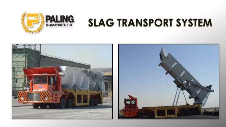
SLAG TRANSPORT SYSTEM
SLIDE 2
WHAT WE DO
§ Heavy load material handling solution providers § Designers and manufacturers of load transporters, load carrying pallets and Slag Transport Systems § Manufacturers of High Capacity Lift Trucks and Coil Handlers
SLIDE 3
THE EAF FOAMED SLAG CHALLENGE
SLIDE 4 MINI MILL SLAG HANDLING CHALLENGES
§ Increased EAF foamed slag handling volumes from larger furnaces and increased
- xygen and carbon injection
§ Reduce energy consumption costs § Reduced heat cycle times to increase tonnage output
SLIDE 5
MINI MILL SLAG HANDLING CHALLENGES CONT.
§ Processing slag, recovering steel § Safety § Reducing operational costs to improve profitability
SLIDE 6
OTHER MINI MILL MATERIAL HANDLING OPERATIONAL CHALLENGES
§ Scrap handling § Downstream product handling and transporting § Process support material handling IE mill scale, sludge, rolls, mill scrap etc. § Increased outsourcing of handling
SLIDE 7
§ Safety § Maintaining customer liquid steel § Increased EAF foamed slag handling volumes § Reducing operational costs maximizing returns to shareholders § Providing expanded services to client base including scrap and downstream finished product handling & transport § Maintain and develop new competitive advantages in service offerings to existing and new customers
THIRD PARTY MILL SERVICE CHALLENGES
SLIDE 8
EAF SLAG FOAMING CHALLENGES
§ Oxygen & Carbon injection reduces electrical energy consumption, causes increased volumes of foamed slag and protects the furnace lining § Reduces tap to tap times increasing production
SLIDE 9 EAF SLAG FOAMING CHALLENGES CONT.
§ Typical operation requires 2 to 3 slag tap off cycles per heat IE 3 slag pot trips to and from disposal sites, usually causing furnace delays due to volume limitations of pots § Fluctuations in foamed slag volumes can exceed the capacity
- f slag pots causing dangerous
- ver flow and furnace cycle
delays
SLIDE 10
§ Cast Iron / Steel Construction § Volume capacity approx. 25 m³ § Industry standard for decades
TYPICAL SLAG POT & CONVENTIONAL CARRIER
SLIDE 11
§ Requires increased capacity slag container and transporting equipment to enable un- interrupted continuous de-slagging with a single slag container removed once - at the end of the heat § Impact – reduce tap to tap times by 33% § Paling Transporter was challenged by a Middle East Steel maker to develop a solution – that is when STS was born
EAF SLAG FOAMING OPERATIONAL SOLUTION
SLIDE 12
SLAG TRANSPORT SYSTEM - ’STS’
SLIDE 13
EVOLUTION TO SLAG HANDLING
SLIDE 14
§ 260% increased slag container volume IE 65 m3 verses 25 m3 standard pots § Transport carrier must be min. 150 tons to 175 tons total payload capacity slag and STS container pallet
CAPACITY & CARRIER REQUIREMENTS
SLIDE 15
§ Stable design § For operator, simplified entry, lift and go § Travel path of transporter protected by container and pallet
STS CONTAINER PALLET AT FURNACE
SLIDE 16
§ High heat resistant steel versus cast iron construction § Refractory lining not required § High slag volume capacity 70+ m3 § Similar dry granular slag base applied prior to filling
STS CONTAINER PALLET
SLIDE 17 § High heat resistant steel § Strength and durability 5x that
§ Formed & fabricated § Greater contact area increases heat dissipation
STS CONTAINER KEY DESIGN FEATURES
SLIDE 18
§ Self opening discharge gate with mechanical linkage controlled by container tilt elevation
STS SLAG CONTAINER DOOR
SLIDE 19
INSIDE THE SEASONED STS CONTAINER
SLIDE 20
ADDITIONAL STS CONTAINER OPERATIONAL BENEFITS
§ Safer container design § More durable container
SLIDE 21 STS - SLAG TRANSPORT SYSTEM DEDICATED SINGLE FUNCTION SLAG POT HANDLER
SLAG DUMP SITE VIEWS
SLIDE 22
§ Elimination of skulls removal and labour- intensive processing § Improved steel recovery in slag processing
ADDITIONAL STS CONTAINER OPERATIONAL BENEFITS - ELIMINATION OF SKULLS
SLIDE 23 ENTER PALLET LIFT & DRIVE
TRANSPORTER OPERATION
SLIDE 24
STS CONTAINER TRANSPORTER
§ Tight turning radius, and high maneuverability required inside most mills
SLIDE 25
§ Double shielded operator cab § High container sides § Transporter can be quickly and safely extracted from under the pallet if required in an emergency
OPERATOR SAFETY
SLIDE 26
STS IN OPERATION
SLIDE 27
ENVIRONMENTAL IMPLICATIONS
SLIDE 28
RADICAL CHANGE IN TECHNOLOGY
SLIDE 29
§ Increased steelmaking tonnage § Fewer slag containers in system lower capital investment § 1 trip versus 2/3 trips per heat to slag dump site § Elimination of stuck skulls and skull processing § Elimination single purpose high investment carriers § Enables business case for introduction of downstream product handling CTS System for further operational cost savings § Enhanced safety
SUMMARY: KEY COST SAVINGS AND ROI CONSIDERATIONS
SLIDE 30
OTHER USES FOR STS
SLIDE 31
§ Standardized pallets adapted to specific handling challenges § Staging of empty and loaded pallets frees transporters to do multiple tasks § Increased efficiency and utilization of handling equipment § Lower total material handling capital investment and operating costs § § “Dumping Capable” pallets § Transporter the base vehicle for STS – functionally similar to scrap dumping pallet
CONTINUOUS TRANSPORT SYTEM - CTS
SLIDE 32
§ Welded steel construction § Versatile flat deck equipped with fixtures to handle virtually any extreme weight / handling characteristic challenge § Standard pallet weight: 20 – 25 tons § “Dumper Capable”
CTS PALLETS
SLIDE 33
STEEL COIL YARD OPERATIONS
SLIDE 34
FINISHED PRODUCT
SLIDE 35
SCRAP HANDLING
SLIDE 36
CHARGE BUCKETS
SLIDE 37
§ Mill rolls spent & finished § Sludge, mill scrap etc.
OTHER PLANT HEAVY ITEM TRANSPORT
SLIDE 38
STS/ CTS TOTAL INTEGRATED TRANSPORTING AND HANDLING SYSTEM
SLIDE 39
§ Increased production tonnage § Improved delivery performance to plant users & customers § Lower material handling equipment investment § Increased productivity § Lower operational costs § Reduced road damage & repair costs § Embrace current world class technology
THE CASE FOR STS & CTS
SLIDE 40
INNOVATION IN LIFTING PROFITS
SLIDE 41
CANADA § CA2641529 USA § US7993573B2 WORLD § WO2007_087726
PATENT REGISTRATIONS