Set-Associative Caches Improve cache hit ratio by allowing a memory - - PDF document

set associative caches
SMART_READER_LITE
LIVE PREVIEW

Set-Associative Caches Improve cache hit ratio by allowing a memory - - PDF document

Set-Associative Caches Improve cache hit ratio by allowing a memory location to be placed in more than one cache block N-Way associative cache allows placement in any block of a set with N elements N is the set-size Number of


slide-1
SLIDE 1

Memory Hierarchy Slide 28 Mark Heinrich & John Hennessy EE182 Winter/98

Set-Associative Caches

  • Improve cache hit ratio by allowing a memory location to

be placed in more than one cache block

— N-Way associative cache allows placement in any block of a set with N elements

  • N is the set-size
  • Number of blocks = N x number of sets
  • Set number is selected by a simple modulo function of the address bits

(The set number is sometimes called the index.)

  • N comparators are needed to search all elements of the set in parallel

— Fully-Associative Cache

  • When there is a single set allowing a memory location to be placed in any

cache block

— Direct-mapped organization can be considered a degenerate set-associative cache with set-size 1

  • For fixed cache capacity, higher associativity leads to

higher hit rates

— Because more combinations of cache lines can be present in the cache at the same time

Memory Hierarchy Slide 29 Mark Heinrich & John Hennessy EE182 Winter/98

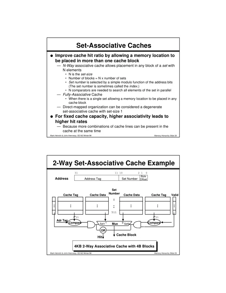
2-Way Set-Associative Cache Example

4KB 2-Way Associative Cache with 4B Blocks

Cache Data Cache Tag

: : :

Cache Data Cache Tag Valid

: : :

Set Number Mux

1 Sel1 Sel0

Cache Block

Compare Adr Tag Compare OR

Hit

:

511

Address

31 11 10 2 1 0

Address Tag Set Number

Byte Offset 21 21

slide-2
SLIDE 2

Memory Hierarchy Slide 30 Mark Heinrich & John Hennessy EE182 Winter/98

Valid Tag Data Set Number

1 511

. . . . . .

XXXX XXXX XXXX XXXX XXXX XXXX XXXX XXXX XXXX XXXX XXXX XXXX XXXX XXXX

Cache Initially Empty

Memory Reference Sequence

  • Look again at the following sequence of memory

references for the previous 2-way associative cache — 0,4,8188,0,16384,0

  • This sequence had 5 misses and 1 hit for the direct-

mapped cache with the same capacity and block size

Memory Hierarchy Slide 31 Mark Heinrich & John Hennessy EE182 Winter/98

Valid Tag Data Set Number

1 511

. . . . . .

1 Memory bytes 0..3 (copy) 000000000000000000000 XXXX XXXX XXXX XXXX XXXX XXXX XXXX XXXX XXXX XXXX XXXX XXXX

After Reference 1

  • Look again at the following sequence of memory

references for the previous 2-way associative cache — 0,4,8188,0,16384,0

Address = 000000000000000000000 000000000 00

Cache Miss, Place in First Block of Set 0

slide-3
SLIDE 3

Memory Hierarchy Slide 32 Mark Heinrich & John Hennessy EE182 Winter/98

Valid Tag Data Set Number

1 511

. . . . . .

1 1 Memory bytes 0..3 (copy) 000000000000000000000 XXXX XXXX Memory bytes 4..7 (copy) 000000000000000000000 XXXX XXXX XXXX XXXX XXXX XXXX XXXX XXXX

After Reference 2

  • Look again at the following sequence of memory

references for the previous 2-way associative cache — 0,4,8188,0,16384,0

Address = 000000000000000000000 000000001 00

Cache Miss, Place in First Block of Set 1

Memory Hierarchy Slide 33 Mark Heinrich & John Hennessy EE182 Winter/98

Valid Tag Data Set Number

1 511

. . . . . .

1 1 1 Memory bytes 0..3 (copy) 000000000000000000000 XXXX XXXX Memory bytes 4..7 (copy) 000000000000000000000 XXXX XXXX XXXX XXXX Memory bytes 8188..8191 (copy) 000000000000000000011 XXXX XXXX

After Reference 3

  • Look again at the following sequence of memory

references for the previous 2-way associative cache — 0,4,8188,0,16384,0 Address = 000000000000000000011 111111111 00

Cache Miss, Place in First Block of Set 511

slide-4
SLIDE 4

Memory Hierarchy Slide 34 Mark Heinrich & John Hennessy EE182 Winter/98

Valid Tag Data Set Number

1 511

. . . . . .

1 1 1 Memory bytes 0..3 (copy) 000000000000000000000 XXXX XXXX Memory bytes 4..7 (copy) 000000000000000000000 XXXX XXXX XXXX XXXX XXXX XXXX Memory bytes 8188..8191 (copy) 000000000000000000011

After Reference 4

  • Look again at the following sequence of memory

references for the previous 2-way associative cache — 0,4,8188,0,16384,0 Address = 000000000000000000000 000000000 00

Cache Hit to First Block in Set 0

Hit

Memory Hierarchy Slide 35 Mark Heinrich & John Hennessy EE182 Winter/98

Valid Tag Data Set Number

1 511

. . . . . .

1 1 1 1 Memory bytes 0..3 (copy) 000000000000000000000 Memory bytes 16384..16387 (copy) 000000000000000001000 Memory bytes 4..7 (copy) 000000000000000000000 XXXX XXXX XXXX XXXX XXXX XXXX Memory bytes 8188..8191 (copy) 000000000000000000011

After Reference 5

  • Look again at the following sequence of memory

references for the previous 2-way associative cache — 0,4,8188,0,16384,0 Address = 000000000000000001000 000000000 00

Cache Miss, Place in Second Block of Set 0

slide-5
SLIDE 5

Memory Hierarchy Slide 36 Mark Heinrich & John Hennessy EE182 Winter/98

Valid Tag Data Set Number

1 511

. . . . . .

1 1 1 1 Memory bytes 0..3 (copy) 000000000000000000000 Memory bytes 16384..16387 (copy) 000000000000000001000 Memory bytes 4..7 (copy) 000000000000000000000 XXXX XXXX XXXX XXXX XXXX XXXX Memory bytes 8188..8191 (copy) 000000000000000000011

After Reference 6

  • Look again at the following sequence of memory

references for the previous 2-way associative cache — 0,4,8188,0,16384,0 Address = 000000000000000000000 000000000 00

Cache Hit to First Block in Set 0 Total of 2 hits and 4 misses

Hit

Memory Hierarchy Slide 37 Mark Heinrich & John Hennessy EE182 Winter/98

Miss Rate vs. Set Size

  • Data is for gcc (compiler execution) for DECStation 3100

with separate code/data 64KB caches using 16B blocks

  • In general, the benefit increasing associativity beyond 2-

4 has minimal impact on miss ratio — 4-way associativity shows more benefit for combined code/data caches

Associativity Instruction Miss Rate Data Miss Rate 1 2.0% 1.7% 2 1.6% 1.4% 4 1.6% 1.4%

slide-6
SLIDE 6

Memory Hierarchy Slide 38 Mark Heinrich & John Hennessy EE182 Winter/98

Miss Rate vs. Set Size

Figure 7.29 from text.

0% 3% 6% 9% 12% 15% Eight-way Four-way Two-way One-way 1 KB 2 KB 4 KB 8 KB Miss rate Associativity 16 KB 32 KB 64 KB 128 KB

Data for SPEC92 on combined code/data cache with 32B block

Memory Hierarchy Slide 39 Mark Heinrich & John Hennessy EE182 Winter/98

Set-Associative Cache Disadvantages

  • N-way Set Associative vs.

Direct Mapped Cache — N comparators vs. 1 — Extra mux delay for data — Data available after Hit/Miss

  • Direct mapped cache:

— Data available before Hit/Miss

  • Assume hit and continue
  • Recover later if miss

Cache Data Cache Tag

: : :

Cache Data Cache Tag Valid

: : :

Set Number Mux

1 Sel1 Sel0

Cache Block

Compare Adr Tag Compare OR

Hit

:

511

21 21

slide-7
SLIDE 7

Memory Hierarchy Slide 40 Mark Heinrich & John Hennessy EE182 Winter/98

Another Extreme: Fully Associative

  • Fully Associative Cache

— push set associative to its limit: only one set!

  • => no set number (or Index)

— Compare the Cache Tags of all cache entries in parallel — Example: Block Size = 32B blocks => N 27-bit comparators — Generally not used for caches because of cost, but fully- associative translation buffers (cover soon) are common :

Cache Data

Byte 31

4 31

:

Cache Tag (27 bits long) Valid Bit

:

Byte 30 Byte 01

:

Byte 63 Byte 62 Byte 32

:

Cache Tag Byte Select Ex: 0x01

= = = = =

Memory Hierarchy Slide 41 Mark Heinrich & John Hennessy EE182 Winter/98

Cache Miss Classification

  • Start by measuring miss rate with an idealized cache

— Ideal is fully associative and infinite capacity — Then reduce capacity to size of interest — Then reduce associativity to degree of interest

  • Compulsory

— First access to a block => cold start — Helps to increase block size and can use prefetching

  • Capacity

— Cache cannot contain all blocks accessed by program — Helps to increase cache size

  • Conflict

— Number of memory locations mapped to a set exceeds the set size — Helps to

  • increase cache size because there are more sets
  • increase associativity
  • Invalidation

— Another processor or I/O invalidates the line — Helps to tune allocation and usage of shared data

slide-8
SLIDE 8

Memory Hierarchy Slide 42 Mark Heinrich & John Hennessy EE182 Winter/98

Cache Block Replacement Policies (Part I)

  • Direct Mapped Cache

— Each memory location mapped to a single cache location — No replacement policy is necessary

  • New item replaces previous item in that cache location
  • Set-Associative Caches

— N-way Set Associative Cache

  • Each memory location has a choice of N cache locations

— Fully Associative Cache

  • Each memory location can be placed in any cache location

— Cache miss handling for set-associative caches

  • Bring in new block from memory
  • Identify a block in the selected set to replace
  • Need to decide which block to replace

Memory Hierarchy Slide 43 Mark Heinrich & John Hennessy EE182 Winter/98

Cache Block Replacement Policies (Part II)

  • Random Replacement

— Hardware randomly selects a cache block to replace — Implementation is actually pseudo-random

  • typically selected by counter or pointer
  • Least Recently Used (LRU)

— Hardware keeps track of access history

  • Maintaining complete usage order for set size N requires log2(N!) bits
  • Replace entry that has not been used for the longest time

— Simple for 2-way associative

  • single bit per set records block in the set that was more/less recently used

— Generally use pseudo-LRU for higher degrees of associativity

  • e.g., 4-way associative uses 3 bits for 2 pairs of entries

— 1 bit for each pair tracks LRU within the pair, another bit tracks LRU between the pairs

  • Optimal Replacement

— Replace the block that will be used latest in the future

  • In practice replacement policy has minor impact on miss rate

— Especially for high associativity — Surprises possible

slide-9
SLIDE 9

Memory Hierarchy Slide 44 Mark Heinrich & John Hennessy EE182 Winter/98

Cache Write Policy

  • Cache read much easier to handle than cache write

— Read does not change value of data

  • Cache write

— Need to keep data in the cache and memory consistent

  • Two options

— Write-Back: write to cache only.

  • Write the cache block to memory when that cache block is being

replaced on a cache miss.

  • Reduces the memory bandwidth required
  • Keep a bit (called the dirty bit) per cache block to track whether the

block has been modified

— Only need to write back modified lines

  • Control can be complex

— Write-Through: write to both cache and memory

  • What!!! How can this be? Isn’t memory too slow for this?

Memory Hierarchy Slide 45 Mark Heinrich & John Hennessy EE182 Winter/98

Processor Cache Write Buffer DRAM

Write Buffer for Write Through

  • Use Write Buffer between the Cache and Memory

— Processor: writes data into the cache and the write buffer — Memory controller: write buffer contents to memory

  • Write buffer is just a FIFO (First-In, First-Out) queue

— Typically small number of entries (4-8) — Works fine if: Rate of stores < 1 / DRAM write cycle — As Rate of stores approaches 1 / DRAM write cycle

  • write buffer fills up
  • stall processor to allow memory to catch up
  • happens due to bursts in write rate even if average rate is OK
slide-10
SLIDE 10

Memory Hierarchy Slide 46 Mark Heinrich & John Hennessy EE182 Winter/98

Cache Performance

  • CPU Time = (CPU Cycles + Memory Stall Cycles) x Clock cycle time
  • Memory system affects

— Memory stall cycles

  • cache miss stalls + write buffer stalls

— Clock cycle time

  • since cache access often determines clock speed for a processor
  • Memory stall cycles = Read stall cycles + Write stall cycles
  • Read stall cycles = Read Miss Rate x #Reads x Read Miss Penalty
  • For write-back cache

Write stall cycles = Write Miss Rate x #Writes x Write Miss Penalty — Or can combine read and write components

  • Memory stall cycles = Miss Rate x #Accesses x Miss Penalty
  • Memory stall CPI = Miss Rate/instruction x Miss Penalty
  • For write-through caches

— Add write buffer stalls

Memory Hierarchy Slide 47 Mark Heinrich & John Hennessy EE182 Winter/98

Cache Performance: Example

  • Assume:

— Miss rate for instructions = 5% — Miss rate for data = 8% — Data references per instruction = 0.4 — CPI with perfect cache = 1.4 — Miss penalty = 20 cycles

  • Find performance relative to perfect cache with no

misses (same clock rate) Misses/instruction = 0.05 + 0.08 x 0.4 = 0.08 Miss stall CPI = 0.08 x 20 = 1.6 — Performance is ratio of CPIs

Performance no misses Performance with . misses = CPI w. misses CPI no misses = 1.4 +1.6 1.4 = 2.1

slide-11
SLIDE 11

Memory Hierarchy Slide 48 Mark Heinrich & John Hennessy EE182 Winter/98

Improving Cache Performance

  • Cache Performance is determined by

Average Memory Access Time = Hit Time + Miss Rate x Miss Penalty

  • Use better technology:

— Use faster RAMs — Cost and availability are limitations

  • Decrease Hit Time

— Make cache smaller, but miss rate increases — Use direct mapped, but miss rate increases

  • Decrease Miss Rate

— Make cache larger, but can increases hit time — Add associativity, but can increase hit time — Increase block size, but increases miss penalty

  • Decrease Miss Penalty

— Reduce transfer time component of miss penalty — Add another level of cache

Memory Hierarchy Slide 49 Mark Heinrich & John Hennessy EE182 Winter/98

Reducing Memory Transfer Time

CPU $ M bus mux CPU $ M bus M M M CPU $ M bus

Solution 1 High BW DRAM Solution 2 Wide Path Between Memory & Cache Solution 3 Memory Interleaving Examples: Page Mode DRAM SDRAM RAMbus

slide-12
SLIDE 12

Memory Hierarchy Slide 50 Mark Heinrich & John Hennessy EE182 Winter/98

Classical DRAM Organization

Row + Column Address Select a single bit

r

  • w

d e c

  • d

e r row address Column Selector & I/O Circuits Column Address data RAM Cell Array word (row) select bit (data) lines

Each intersection represents a 1-T DRAM Cell

Memory Hierarchy Slide 51 Mark Heinrich & John Hennessy EE182 Winter/98

Cycle Time versus Access Time

  • DRAM Cycle Time >> DRAM Access Time
  • DRAM (Read/Write) Cycle Time :

—How frequently can you initiate an access?

  • DRAM (Read/Write) Access Time:

—How quickly will you get what you want once you initiate an access?

Time Access Time Cycle Time

slide-13
SLIDE 13

Memory Hierarchy Slide 52 Mark Heinrich & John Hennessy EE182 Winter/98

Fast Page Mode DRAM

  • Regular DRAM Organization

— N rows x N column x M-bit wide — Read & Write M-bit at a time — Each M-bit access requires RAS / CAS cycle

  • Fast Page Mode DRAM

— N x M “register” to save a row — only CAS is needed

N rows N cols DRAM M bits Row Address Column Address M-bit Output

Memory Hierarchy Slide 53 Mark Heinrich & John Hennessy EE182 Winter/98

Increasing Bandwidth By Interleaving

Access Pattern without Interleaving:

Start Access for D1

CPU Memory

Start Access for D2 D1 available

Access Pattern with 4-way Interleaving:

Access Bank 0 Access Bank 1 Access Bank 2 Access Bank 3

We can Access Bank 0 again CPU

Memory Bank 1 Memory Bank 0 Memory Bank 3 Memory Bank 2

slide-14
SLIDE 14

Memory Hierarchy Slide 54 Mark Heinrich & John Hennessy EE182 Winter/98

Cache Summary

  • Principle of Locality:

— Temporal Locality: Locality in Time — Spatial Locality: Locality in Space

  • Cost/performance tradeoff in memory technologies
  • Three Major Categories of Cache Misses

— Compulsory Misses: first-time access — Capacity Misses: increase cache size — Conflict Misses: increase associativiy or size

  • Write Policy

— Write-Through: use a write buffer, high memory BW — Write-Back: control can be complex, but low memory BW

Memory Hierarchy Slide 55 Mark Heinrich & John Hennessy EE182 Winter/98

Virtual Memory

  • Provides appearance of very large memory

— Total memory for all jobs >> physical memory — Address space of each job > physical memory

  • Allows available (fast and expensive) physical memory

to be utilized effectively

  • Simplifies memory management
  • Exploits hierarchy to reduce average access time
  • Uses 2 storage levels

— primary (main) and secondary

  • Distinguish between virtual and physical addresses

— Virtual address is used by the programmer to address memory within a process’s address space — Physical address is used by the hardware to access a physical memory location

slide-15
SLIDE 15

Memory Hierarchy Slide 56 Mark Heinrich & John Hennessy EE182 Winter/98

Virtual Memory (VM) Basics

  • Maps virtual addresses to physical addresses

— called (dynamic) address translation — provides protection and sharing between processes

  • Data missing from main memory must be transferred

from secondary memory (disk) — Misses handled by operating system

  • miss time very large so OS manages the hierarchy and schedules

another process instead of stalling (context switch)

— Architectures support either variable or fixed-size data transfers

  • fixed-size is most common now

— Placement of blocks in memory depends on choice of fixed vs. variable — Blocks can be fetched when needed or prefetched in advance

Memory Hierarchy Slide 57 Mark Heinrich & John Hennessy EE182 Winter/98

Fixed vs. Variable Blocks

  • Allocation

— Easier to allocate fixed-size blocks because a block from secondary storage can be placed in any free main memory location — Variable-size blocks require search for free main memory location of adequate size

  • Fragmentation => free memory that cannot be allocated

— Variable=Size blocks exhibit external fragmentation

  • There may be sufficient free main memory to hold a block, but the free

locations are scattered among variable size blocks

— Fixed-Size blocks exhibit internal fragmentation

  • program is allocated an integral no. of fixed sized blocks, so part of the

last block is "wasted”

  • The impact can be minimized by selecting small block sizes relative to

program requirements and main memory capacity

slide-16
SLIDE 16

Memory Hierarchy Slide 58 Mark Heinrich & John Hennessy EE182 Winter/98

Address Translation

  • Program uses virtual addresses

— Relocation => a program can be loaded anywhere in physical memory without recompiling or re-linking

  • Memory accessed with physical addresses
  • ISA defines the interface between OS and Hardware to

specify the virtual-to-physical translation

— When a virtual address is missing from main memory, the OS handles the miss

  • read the missing data, create the translation, return to re-execute the

instruction that caused the miss

Address Translation fault handler (in OS) Main Memory Secondary Memory Virtual address missing item fault valid physical address

OS performs this transfer

Memory Hierarchy Slide 59 Mark Heinrich & John Hennessy EE182 Winter/98

Exceptions

  • Conditions and events that cause transfer to the OS

— Examples

  • integer overflow, translation fault, HW failure, I/O interrupt
  • OS handles exception and may restart execution

— Saves state of executing process, including address of the instruction that caused the exception — Determine cause of exception

  • exception vector address: address where OS is initiated
  • register that records reasons (MIPS Cause register)

— May need to restart instruction as if nothing happened

  • Hardest type of exceptions
  • Page faults are like these–transparent to the user
  • Hardware may implement precise exceptions

— “Hardware stops on a dime”– no extra instructions executed

  • Or SW may need to do extra work to recover state changes
slide-17
SLIDE 17

Memory Hierarchy Slide 60 Mark Heinrich & John Hennessy EE182 Winter/98

Implementing Protection

  • The address translation mechanism allows multiple

users (and the OS) to use portions of main memory while maintaining protection from other users

  • Each process has its own address space

— process = address space + processor state (registers + PC)

  • address space contains code + data
  • active when the process is running on CPU

— processor state loaded (including PC), address space mapped

  • process state = everything that needs to be saved and restored to stop

and restart process

— Compiler, linker, and loader are simplified because they see only the virtual address space abstracted from physical memory allocation

  • How does this happen?

— Each process has its own translation table set up by the OS — Therefore, a process can only access only what the OS allocates and permits

Memory Hierarchy Slide 61 Mark Heinrich & John Hennessy EE182 Winter/98

page

reg cache

memory

disk

frame

Paged Virtual Memory

  • Most common form of address translation

— Virtual and physical address space partitioned into blocks of equal size — Virtual address space blocks are called pages — Physical address space blocks are called frames (or page frames)

  • Placement

— Any page can be placed in any frame (fully-associative)

  • Pages are fetched on demand
slide-18
SLIDE 18

Memory Hierarchy Slide 62 Mark Heinrich & John Hennessy EE182 Winter/98

Paging Organization

  • Paging can map any virtual page to any physical frame

Physical addresses Disk addresses Virtual addresses Address translation

Memory Hierarchy Slide 63 Mark Heinrich & John Hennessy EE182 Winter/98

Mapping Process

  • Mapping is done by a page table kept in memory
  • Page size is power of two:

— physical frame address replaces virtual page address — lower portion (page offset or displacement) is unchanged

Virtual address

page number

  • ffset

12

Page Table

index page table Page Table Base Register

V Access Rights Frame

table located in physical memory physical address

20

  • ffset

frame # 12 20

To memory

Valid bit = 1 => virtual page is valid & mapped Access rights: define permitted accesses (Read, Write, Execute)

slide-19
SLIDE 19

Memory Hierarchy Slide 64 Mark Heinrich & John Hennessy EE182 Winter/98

Address Translation Algorithm

  • If V=1, the mapping is valid

— CPU checks permissions (R,R/W,X) against access type

  • if access is permitted, generates physical address and proceeds

— If access is not permitted, generates a protection fault.

  • If V != 1, the mapping is invalid

— CPU generates a page fault

  • Faults are exceptions handled by the OS

— Page faults

  • The OS fetches the missing page, creates a map entry, and restarts the

process

  • another user process is switched in to execute while the page is brought

from disk

— Protection faults

  • Checks whether it is a programming error or permission needs to be

changed

Memory Hierarchy Slide 65 Mark Heinrich & John Hennessy EE182 Winter/98

Page Replacement and Write Policies

  • When a page fault occurs, choose a page to replace

— Fully associative so any frame/page is a candidate — Choose empty one if it exists. — Choose either (just as we did for cache):

  • LRU: approximated with Reference or Use bit in page table

— true LRU is too hard, since we would need to track the time of use or every page frame — Commonly used clock algorithms: resets Use bits periodically

  • Random: approximate as we did for cache
  • Write policy: Always write-back

— Keep a dirty bit

  • Set to 1 if page is modified
  • When a modified page is replaced, the OS writes it back to disk

— Many systems use SW page cleaner to write-back modified pages when the disk would be idle

  • Makes selection of replacement more efficient
slide-20
SLIDE 20

Memory Hierarchy Slide 66 Mark Heinrich & John Hennessy EE182 Winter/98

Segmentation

  • Virtual memory with variable sized segments
  • Provides relocation as well as virtualization
  • Can be applied instead of or combined with paging

Present Access Length Phy Addr segment # displacement

Segment Table

segment length

+ physical address

Presence (Valid) Bit

Segment Table Base Register

virtual address

access rights

>

protection error

Memory Hierarchy Slide 67 Mark Heinrich & John Hennessy EE182 Winter/98

Segmented Address Translation

  • Three major drawbacks:

— Segment register is separate part of the address

  • done to expand address space beyond word length
  • segmentation yields a nonlinear address space
  • segments are visible to programmer, since must specify a segment

number and segments are not adjacent

  • unless segment is large enough for all code or data, it creates

programming difficulties or inefficiencies

— Placing variable sized objects is hard

  • not simple like fixed-sized pages

— External fragmentation wastes memory, especially if wide variation in block size

  • Another kind of segmentation

— Fixed-size segments on top of pages (MSBs = segment #) — Goal: to conserve and manage page table space — Called “segments”, but different: none of above drawbacks

slide-21
SLIDE 21

Memory Hierarchy Slide 68 Mark Heinrich & John Hennessy EE182 Winter/98

Choosing a Page Size

  • Factors favoring large pages

— smaller page tables — more efficient for large programs and large memories

  • fewer page faults, more efficient disk transfer
  • Factors favoring smaller pages

— time to start-up small processes (only a few pages) — internal fragmentation (significant only for small programs)

  • General trend is towards large pages

— 1978: 512 B — 1984: 4 KB — 1990: 16 KB — 199x: 64 KB

  • Many recent machines support multiple page sizes to

balance competing factors

Memory Hierarchy Slide 69 Mark Heinrich & John Hennessy EE182 Winter/98

Valid Virtual Address Physical Address Dirty Access Rights

Typical TLB Entry

Making VM Fast: TLBs

  • If page table is kept in memory

— all memory references require two accesses

  • one for page table entry and one to get the actual data.
  • Translation Lookaside Buffer (TLB)

— Hardware maintains a cache of recently-used page table translations — Look up all accesses up in TLB

  • Hit in TLB gives the physical page number
  • Miss in TLB => get translation from the page table and reload

— TLB usually smaller than cache (each entry maps a full page)

  • more associativity possible and common
  • similar speed to cache access
  • contains all bits needed to translate address, implement VM
slide-22
SLIDE 22

Memory Hierarchy Slide 70 Mark Heinrich & John Hennessy EE182 Winter/98

Virtual Memory and Cache

  • OS manages memory hierarchy between secondary storage and main memory

— Allocates physical memory to virtual memory and specifies the mapping to hardware through page tables

  • Hardware caches recently used page table entries in the Translation Lookaside Buffer

CPU Cache Virtual Memory/ Secondary Storage Physical Memory/ Main Memory/ Primary Storage Page Tables Address Translation Page Faults TLB Address Unit Cache Misses TLB Misses Virtual Address Physical Address

Memory Hierarchy Slide 71 Mark Heinrich & John Hennessy EE182 Winter/98

Memory access with a TLB

  • Access TLB to get physical address

—Miss: access memory to get translation

  • Access cache to get data

—Miss: access memory to get data

  • Optimization: access TLB and cache in parallel

TLB Lookup Cache Main Memory Virtual Addr Phy Addr miss hit data hit miss

CPU

map entry data Access page tables for translation (from memory!) Page table at known physical address, can access with page table or TLB look-up.

slide-23
SLIDE 23

Memory Hierarchy Slide 72 Mark Heinrich & John Hennessy EE182 Winter/98

Common Memory Hierarchy Framework

  • Block placement

— Direct-Mapped — Set-Associative — Fully-Associative

  • Replacement policy

— Random — LRU

  • Write policy

— Write-Back — Write-Through

Memory Hierarchy Slide 73 Mark Heinrich & John Hennessy EE182 Winter/98

Memory Hierarchy Characteristics

  • Performance and cost drive different characteristics

through the hierarchy — Access times to levels — Size and cost — Function and program behavior Hierarchy Blocks Block Size Miss Handling Caches Fixed 16-128 B Hardware Paging Fixed 4KB-64KB SW Segments Variable SW TLBs Fixed 1-2 PTEs SW or HW

slide-24
SLIDE 24

Memory Hierarchy Slide 74 Mark Heinrich & John Hennessy EE182 Winter/98

Pentium Pro Processor Memory Hierarchy

  • Virtual Memory

— 32-bit virtual address 32-bit physical address — 4KB page size — TLB organization

  • split code/data TLBs
  • 32-entry code; 64-entry data
  • 4-way associative
  • pseudo-LRU replacement
  • Cache

— Level-1 on CPU-chip

  • split code/data
  • 8KB capacity
  • 32B blocks
  • 4-way associative
  • pseudo-LRU replacement

— Level-2 cache off CPU-chip

  • combined code/data
  • 1MB capacity
  • 32B blocks
  • 4-way associative
  • pseudo-LRU replacement

Photograph from Intel.

Memory Hierarchy Slide 75 Mark Heinrich & John Hennessy EE182 Winter/98

Summary

  • Two Different Types of Locality

— Temporal Locality (Locality in Time

  • The location of a memory reference is likely to be the same as another

recent reference

— Spatial Locality (Locality in Space)

  • The location of a memory reference is likely to be near another recent

reference

  • Memory hierarchies exploit locality

— Present the user with the memory capacity of the least expensive technology at a speed near that of the fastest technology

  • DRAM is inexpensive, but slow

— Good choice for presenting the user with a BIG memory system

  • SRAM is fast, but expensive

— Good choice for providing the user FAST access time.

slide-25
SLIDE 25

Memory Hierarchy Slide 76 Mark Heinrich & John Hennessy EE182 Winter/98

The Future

  • Memory Hierarchies will continue to be an area of great

importance — Growing gap between CPU performance and disk/DRAM access time — Innovative approaches needed to

  • Avoid degrading performance by the slowest technology
  • Keep costs and power consistent with system requirements
  • There are many issues in memory hierarchies we have

not had time to discuss — multilevel caches — sub-blocking — MP consistency — TLB design — virtual caches — write combining