Session 4: Interaction Region Subgroup Chairs: Fulvia Pilat, Tom - - PowerPoint PPT Presentation

session 4 interaction region subgroup chairs fulvia pilat
SMART_READER_LITE
LIVE PREVIEW

Session 4: Interaction Region Subgroup Chairs: Fulvia Pilat, Tom - - PowerPoint PPT Presentation

Session 4: Interaction Region Subgroup Chairs: Fulvia Pilat, Tom Markiewicz (Tuesday afternoon) Thermal Shield and Cold Quadrupole Coil Layers Mass Support Structure y off QD0 e + 4.8 m 1 cm BNL Small Coil Test Winding Coil Support


slide-1
SLIDE 1

BNL Small Coil Test Winding

Session 4: Interaction Region Subgroup Chairs: Fulvia Pilat, Tom Markiewicz (Tuesday afternoon)

1 cm

LHe Flow Space Coil Support Tubes Sextupole Coil Quadrupole Coil Layers Thermal Shield and Cold Mass Support Structure

QD0 e+

yoff

4.8 m

slide-2
SLIDE 2

Linear Collider Final Focus Magnet Issues (Top Level).

IR magnet design optimization (beam aperture, field requirements, coil/pm–material layout, vacuum, energy deposition, support etc.).

slide-3
SLIDE 3

For QDO G = 144 T/m Rapt = 10 mm

  • Permanentmagnet.
  • Gradient is fixed...
  • Except for changes

duetosolenoid.

slide-4
SLIDE 4
  • Large aperture superconducting magnet

(has both beams in the central region).

  • Vertical extraction via electrostatic separator

at 20 m and a shielded septum at 50 m.

The TESLA and JLC Final Focus Quadrupole Concepts.

  • Iron magnet inside a superconducting

compensator magnet (avoid saturation, buck out detector solenoid field).

  • Extract the beam through coil pocket.

Incoming Beam Extracted Beam

Yoke

57 mm

slide-5
SLIDE 5

Recent Winding Tests on Small Diameter Support Tubes

Tube OD = 1.5" Rcoil = 19.4 mm Tube OD = 1.5" Rcoil = 19.4 mm

  • Need to make small diameter coils

(which then have tight bends).

  • Wind with single strand conductor
  • n inner layers and 6-around-1 cable

for outer layers (see winding machine).

  • Then can keep cryostat small enough

to pass disrupted beam outside.

slide-6
SLIDE 6

Superconducting Magnets for the HERA Luminosity Upgrade.

slide-7
SLIDE 7

QD0 Cross Section with 4°K Beam Tube and Sextupole Winding.

1 cm

LHe Flow Space Coil Support Tubes Sextupole Coil Quadrupole Coil Layers Thermal Shield and Cold Mass Support Structure

QDO Coil Parameters

Sextupole 1300 T/m² Inner Quad 51 T/m Outer Quad 93 T/m Total Quad 144 T/m Inner Beam Tube 20 mm ID Outer Cryostat Tube 114 mm OD

slide-8
SLIDE 8

Estimating the fringe field from NLC final focus quadrupoles.

OPERA-2d

Pre and Post-Processor 8.014

OPERA-2d

Pre and Post-Processor 8.014

0.0 40.0 80.0 120.0 160.0 200.0 240.0 280.0 320.0 360.0 0.0 20.0 40.0 60.0 80.0 100.0 120.0 140.0 160.0 180.0 200.0 220.0 240.0 0.0 40.0 80.0 120.0 160.0 200.0 240.0 280.0 320.0 360.0 0.0 20.0 40.0 60.0 80.0 100.0 120.0 140.0 160.0 180.0 200.0 220.0 240.0

Y [mm]

  • 0.005

0.0 0.005 Homogeneity of BMOD*(X**2+Y**2)**1.5 w.r.t. value 369

  • 0.005

0.0 0.005 54.6736 at (200.0,60.0)

X [mm]

± 1×10⁻³

Outside the coil: Bx ∝ sin(3θ)/R3 By ∝ cos(3θ)/R3 So |B|·R3 is a constant

Outside the coil B-field is quite predicable and rapidly becomes small in magnitude.
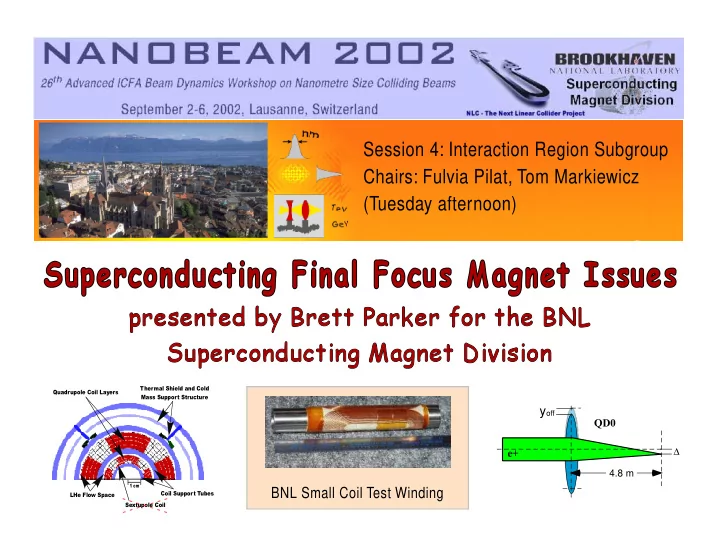
NLC Detector

(m) (m)

slide-9
SLIDE 9

Tom Markiewicz

NLC - The Next Linear Collider Project

e+,e- pairs from beams. γ interactions

# pairs scales w/ Luminosity 1-2x10⁹/sec 0.85 mW per side BSOL, L*,& Masks Luminosity Monitor & Pair Monitor will Shield QD

slide-10
SLIDE 10

Tom Markiewicz

NLC - The Next Linear Collider Project

e,γ,n secondaries made when pairs hit high Z surface of LUM or Q1

High momentum pairs mostly in exit beampipe Low momentum pairs trapped by detector solenoid field

slide-11
SLIDE 11

160 0.03 0.06 0.09 0.12 200 400 600 800 40 80 120 . (km) D (m)

x y

D x

β

NLC Beam Delivery System: Final Focus Optics Summary.

Distance (m)

Optics of the NLC Final Focus

β*x,y = 8., 0.11 mm

  • Extreme vertical demagnification at IP

.

  • Sextupoles needed to correct chromaticity

(compensate for momentum spread).

  • Beam sizes σx/σy = 243./3.0 nm at IP

(but a few tenths of a mm in FF doublet).

  • Small kicks in FF doublet can cause beams

to miss each other (Y–offset sensitivity).

FF doublet

β β

slide-12
SLIDE 12

QD0 e+

yoff P = 250 GeV/c Bρ = 834 T·m G = 144 T/m

σy = 0.11 mm

∆θy = 0.74 nr

σy =

3 nm L* = 3.8 m Lm = 2 m Let yoff = 1 nm, then ∆B = 1.44e-7 T

θ = 2 · 1.44e-7

834 = 0.34e-9 radians

4.8 m

θ·L = 4.8 · 3.4e-10 = 1.6e-9 m

QD0 IP QD0 QD0 QD0

NLC Beam Delivery System: Quadrupole Offset Sensitivity.

slide-13
SLIDE 13

Seismic Isolation Issues (ground motion).

Many groups are actively working in this area. Indepen- dent of the type of magnet used there will have to be some system that will perform active seismic isolation. It will be assumed that any superconducting magnet system will be mounted on an active isolation platform.

slide-14
SLIDE 14

M o t i o n c a u s e d b y t h e cryogenic system.

Various cryogenic system configurations will have to be investigated. These configurations will have to minimize any motion the cryogenic system might create in the cryostat and/or cold mass. Different cooling schemes will have to be looked into to see which one will produce the smallest vibration. Some choices could be forced flow, 4.2°K helium, 1.8°K superfluid or conduction cooling for the magnet. It will be important to develop a model of the mechanical system. This model can be used to investigate what influence the connection components (bellows, flex hoses, straps, posts etc.) will have in enhancing or minimizing vibration of cold mass relative to the cryostat. Also passive isolation techniques should be incorporated in any design.

slide-15
SLIDE 15

Active vibration isolation

  • f the cold mass.

The choice of cooling scheme, mechanical design, and passive damping will be required to minimize vibration of the cold mass to a level that an active system can reduce further to the nanometer level. Use of existing nanometer positioning sensors, piezoelectric actuators, and low noise accelerometers will need to be investigated for use in a cryogenic system and in the presence of a moderate magnetic field. These sensors and actuators are currently being used in active vibration isolation systems. The technology used in these sensors and actuators should allow them to perform in this environment but an active isolation system for the cold mass will require six degrees of freedom. This will mean that many sensors and actuators will be needed and a DSP based control system will be needed for feedback, feed-forward, and sensor processing.