Lecture 7: Sequential Networks: Registers, Finite State Machines
CSE 140: Components and Design Techniques for Digital Systems
Diba Mirza
- Dept. of Computer Science and Engineering
University of California, San Diego
1
Registers, Finite State Machines CSE 140: Components and Design - - PowerPoint PPT Presentation
Lecture 7: Sequential Networks: Registers, Finite State Machines CSE 140: Components and Design Techniques for Digital Systems Diba Mirza Dept. of Computer Science and Engineering 1 University of California, San Diego D Flip-Flop (Delay)
Diba Mirza
University of California, San Diego
1
Id D Q(t) Q(t+1) 0 0 0 0 1 0 1 0 2 1 0 1 3 1 1 1
2
What does the equation mean?
3
4
Clk
rising edges
Clk
falling edges Internal design: Just invert servant clock rather than master The triangle means clock input, edge triggered
Internal Circuit D Q CLK EN D Q 1 D Q EN Symbol
6
7
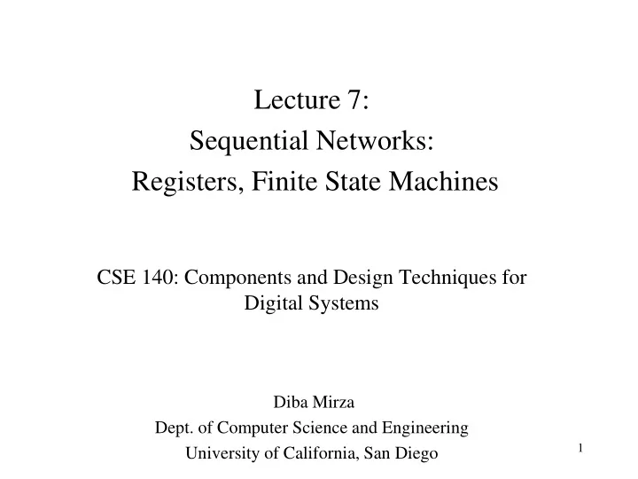
D flip-flop D latch master D latch servant DmQm C m Ds D Clk Qs’ Cs Qs Q’ Q S R D Q C D latch
Only loads D value present at rising clock edge, so values can’t propagate to other flip- flops during same clock cycle. Tradeoff: uses more gates internally than D latch, and requires more external gates than SR – but gate count is less of an issue today. SR can’t be 11 if D is stable before and while C=1, and will be 11 for only a brief glitch even if D changes while C=1. Problem: C=1 too long propagates new values through too many latches: too short may not enable a store.
S1 R1 S Q C R Level-sensitive SR latch
S and R only have effect when C=1. We can design outside circuit so SR=11 never happens when C=1. Problem: avoiding SR=11 can be a burden.
R (reset) S (set) Q SR latch
S=1 sets Q to 1, R=1 resets Q to 0. Problem: SR=11 yield undefined Q.
8
9
D Q D Q D Q D Q IN OUT1 OUT2 OUT3 OUT4 CLK
10
D Q D Q D Q D Q IN OUT1 OUT2 OUT3 OUT4 CLK OUT
11
D Q D Q D Q D Q IN OUT1 OUT2 OUT3 OUT4 CLK
12
Active Inactive
13
14
CLK Q1 Q0
15
16
CLK
17
S0 S1 S2 S3
Q1(t) Q0(t) Q1(t+1) Q0(t+1) Current state Next State S0 S1 S1 S2 S2 S3 S3 S0
18
Q1(t) Q0(t) Q1(t+1) Q0(t+1) 1 1 1 1 1 1 1 1
PI Q: Which of the following is the likely structure of the circuit realization of the counter Q0(t) Q1(t)
D Q Q’ D Q Q’
Combinational circuit Combinational circuit
Q0(t) Q1(t)
Q D Q Q’
Combinational circuit
19
Q1(t) Q0(t) Q1(t+1) Q0(t+1) 1 1 1 1 1 1 1 1
Q0(t) Q1(t)
D Q Q’ D Q Q’
Combinational circuit D0(t) = Q0(t)’ D1(t) = Q0(t) Q1(t)’ + Q0(t)’ Q1(t)
20
Q1(t) Q0(t) Q1(t+1) Q0(t+1) 1 1 1 1 1 1 1 1
We store the current state using D-flip flops so that:
don’t change while the next output is being computed
Q0(t) Q1(t)
D Q Q’ D Q Q’
Q0(t+1) = Q0(t)’ Q1(t+1) = Q0(t) Q1(t)’ + Q0(t)’ Q1(t)
21
22
CLK x(t) y(t)
S(t)
CLK x(t) y(t)
S(t)