
SLIDE 1
Recall: Liang‐Barsky 3D Clipping
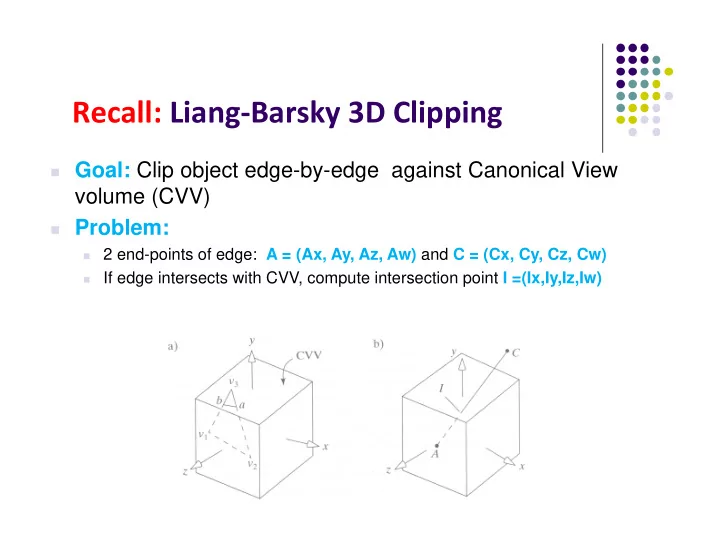
Goal: Clip object edge-by-edge against Canonical View
volume (CVV)
Problem:
2 end-points of edge: A = (Ax, Ay, Az, Aw) and C = (Cx, Cy, Cz, Cw)
If edge intersects with CVV, compute intersection point I =(Ix,Iy,Iz,Iw)