
SLIDE 1
www.rbf-morph.com RBF Morph, an ANSYS Inc. Partner ANSYS Training 2012
RBF Morph Training Agenda Session #1 (May 24, 2:00 PM India Time, - - PowerPoint PPT Presentation
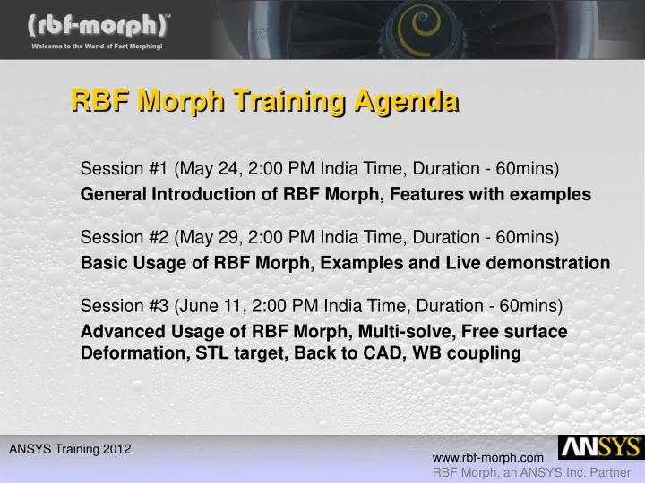
RBF Morph Training Agenda Session #1 (May 24, 2:00 PM India Time, Duration - 60mins) General Introduction of RBF Morph, Features with examples Session #2 (May 29, 2:00 PM India Time, Duration - 60mins) Basic Usage of RBF Morph, Examples and Live
www.rbf-morph.com RBF Morph, an ANSYS Inc. Partner ANSYS Training 2012
www.rbf-morph.com RBF Morph, an ANSYS Inc. Partner ANSYS Training 2012
www.rbf-morph.com RBF Morph, an ANSYS Inc. Partner ANSYS Training 2012
www.rbf-morph.com RBF Morph, an ANSYS Inc. Partner ANSYS Training 2012
www.rbf-morph.com RBF Morph, an ANSYS Inc. Partner ANSYS Training 2012
www.rbf-morph.com RBF Morph, an ANSYS Inc. Partner ANSYS Training 2012
www.rbf-morph.com RBF Morph, an ANSYS Inc. Partner ANSYS Training 2012
approach based on state-of-the-art RBF (Radial Basis Functions) techniques .
compatible with the mesh topology, directly in the solving stage, just adding a single command line in the input file:
typical of the fluid-dynamic design like:
www.rbf-morph.com RBF Morph, an ANSYS Inc. Partner ANSYS Training 2012
www.rbf-morph.com RBF Morph, an ANSYS Inc. Partner ANSYS Training 2012
N i i i
1
4 3 1
www.rbf-morph.com RBF Morph, an ANSYS Inc. Partner ANSYS Training 2012
N i k i k k
i i i
1
T
j i
k k ij
2 2 2 1 1 1 N N N
k k k k k k k k k
z y x z y x z y x P
www.rbf-morph.com RBF Morph, an ANSYS Inc. Partner ANSYS Training 2012
Radial Basis Function
) (r
Spline type (Rn)
n
r
, n odd Thin plate spline (TPSn)
r r
n log
, n even Multiquadric(MQ)
2
1 r
Inverse multiquadric (IMQ)
2
1 1 r
Inverse quadratic (IQ)
2
1 1 r
Gaussian (GS)
2
r
e
z y x s v z y x s v z y x s v
z z z z N i k z i z z y y y y N i k y i y y x x x x N i k x i x x
i i i
4 3 2 1 1 4 3 2 1 1 4 3 2 1 1
x x x x x x x x x
www.rbf-morph.com RBF Morph, an ANSYS Inc. Partner ANSYS Training 2012
www.rbf-morph.com RBF Morph, an ANSYS Inc. Partner ANSYS Training 2012
#points 2010 (Minutes) 2008 (Minutes) 3.000 0 (1s) 15 10.000 0 (5s) 120 40.000 1 (44s) Not registered 160.000 4 Not registered 650.000 22 Not registered 2.600.000 133 Not registered
www.rbf-morph.com RBF Morph, an ANSYS Inc. Partner ANSYS Training 2012
www.rbf-morph.com RBF Morph, an ANSYS Inc. Partner ANSYS Training 2012
www.rbf-morph.com RBF Morph, an ANSYS Inc. Partner ANSYS Training 2012
www.rbf-morph.com RBF Morph, an ANSYS Inc. Partner ANSYS Training 2012
www.rbf-morph.com RBF Morph, an ANSYS Inc. Partner ANSYS Training 2012
www.rbf-morph.com RBF Morph, an ANSYS Inc. Partner ANSYS Training 2012
www.rbf-morph.com RBF Morph, an ANSYS Inc. Partner ANSYS Training 2012
www.rbf-morph.com RBF Morph, an ANSYS Inc. Partner ANSYS Training 2012
www.rbf-morph.com RBF Morph, an ANSYS Inc. Partner ANSYS Training 2012
www.rbf-morph.com RBF Morph, an ANSYS Inc. Partner ANSYS Training 2012
www.rbf-morph.com RBF Morph, an ANSYS Inc. Partner ANSYS Training 2012
www.rbf-morph.com RBF Morph, an ANSYS Inc. Partner ANSYS Training 2012
www.rbf-morph.com RBF Morph, an ANSYS Inc. Partner ANSYS Training 2012
www.rbf-morph.com RBF Morph, an ANSYS Inc. Partner ANSYS Training 2012
www.rbf-morph.com RBF Morph, an ANSYS Inc. Partner ANSYS Training 2012
www.rbf-morph.com RBF Morph, an ANSYS Inc. Partner ANSYS Training 2012
www.rbf-morph.com RBF Morph, an ANSYS Inc. Partner ANSYS Training 2012
www.rbf-morph.com RBF Morph, an ANSYS Inc. Partner ANSYS Training 2012
www.rbf-morph.com RBF Morph, an ANSYS Inc. Partner ANSYS Training 2012
www.rbf-morph.com RBF Morph, an ANSYS Inc. Partner ANSYS Training 2012
Graphics Sidebar Main Sidebar Common Buttons Switchable Panel
www.rbf-morph.com RBF Morph, an ANSYS Inc. Partner ANSYS Training 2012
www.rbf-morph.com RBF Morph, an ANSYS Inc. Partner ANSYS Training 2012
Active Encap Parameters Encap Shape Setup from Parts Encap kind Multi Encap Management
www.rbf-morph.com RBF Morph, an ANSYS Inc. Partner ANSYS Training 2012
Surfaces Surface Borders Collect the points from all sets Number of sets Set the movement
www.rbf-morph.com RBF Morph, an ANSYS Inc. Partner ANSYS Training 2012
Active Point Parameters Import from file Finalize and show
www.rbf-morph.com RBF Morph, an ANSYS Inc. Partner ANSYS Training 2012
Collect all the Source Points Load/Save a solution file Solve the RBF Problem
www.rbf-morph.com RBF Morph, an ANSYS Inc. Partner ANSYS Training 2012
Desired amplification Surfaces to be previewed Export animation frames Amplification range for animation
www.rbf-morph.com RBF Morph, an ANSYS Inc. Partner ANSYS Training 2012
Desired amplification Fluid Zones affected by the morpher Show Negative Volumes Morph the Volume Mesh Restore the
www.rbf-morph.com RBF Morph, an ANSYS Inc. Partner ANSYS Training 2012
www.rbf-morph.com RBF Morph, an ANSYS Inc. Partner ANSYS Training 2012
www.rbf-morph.com RBF Morph, an ANSYS Inc. Partner ANSYS Training 2012
www.rbf-morph.com RBF Morph, an ANSYS Inc. Partner ANSYS Training 2012
www.rbf-morph.com RBF Morph, an ANSYS Inc. Partner ANSYS Training 2012
www.rbf-morph.com RBF Morph, an ANSYS Inc. Partner ANSYS Training 2012
www.rbf-morph.com RBF Morph, an ANSYS Inc. Partner ANSYS Training 2012
www.rbf-morph.com RBF Morph, an ANSYS Inc. Partner ANSYS Training 2012
www.rbf-morph.com RBF Morph, an ANSYS Inc. Partner ANSYS Training 2012
www.rbf-morph.com RBF Morph, an ANSYS Inc. Partner ANSYS Training 2012
www.rbf-morph.com RBF Morph, an ANSYS Inc. Partner ANSYS Training 2012
www.rbf-morph.com RBF Morph, an ANSYS Inc. Partner ANSYS Training 2012
www.rbf-morph.com RBF Morph, an ANSYS Inc. Partner ANSYS Training 2012
www.rbf-morph.com RBF Morph, an ANSYS Inc. Partner ANSYS Training 2012
www.rbf-morph.com RBF Morph, an ANSYS Inc. Partner ANSYS Training 2012
www.rbf-morph.com RBF Morph, an ANSYS Inc. Partner ANSYS Training 2012
www.rbf-morph.com RBF Morph, an ANSYS Inc. Partner ANSYS Training 2012
www.rbf-morph.com RBF Morph, an ANSYS Inc. Partner ANSYS Training 2012
www.rbf-morph.com RBF Morph, an ANSYS Inc. Partner ANSYS Training 2012
www.rbf-morph.com RBF Morph, an ANSYS Inc. Partner ANSYS Training 2012
www.rbf-morph.com RBF Morph, an ANSYS Inc. Partner ANSYS Training 2012