
Special Report supplement | February 2012 | broadcastengineering.com 39
R
- uters have been present in the
broadcast industry for a long time; I was in school when the first re- dundant router was introduced. The reason for redundancy is quite simple: Viewers do not like to see messages like “Com- ing soon” or “Technical difficulties, please wait.” Imagine the stress in the studio to re- solve these issues. These days, critical equip- ment on the live path has built-in redundan- cy, or at least an automatic changeover (ACO) implemented to make sure that viewers do not see the screen in Figure 1 too often. There are two main categories of routers: video and audio. Nowadays, these two types can be combined to form one signal router in- side the studio. Another major trend is the IP router and agnostic (universal) router, thanks to SFPs and emSFPs, capable of transporting any type of signals over any media (coaxial, fiber, Ethernet, etc.). The behavior of the traditional broadcast router is simple. It takes numerous inputs and reroutes, or connects, these inputs to numer-
- us output ports. This is the basic function
- f the video and audio router. The second
important task of the router is to correctly switch the output source (i.e., output 1 equals input 1 and will be changed for input 2) at the correct time and even perform glitch- free switching (i.e., no error in the data
- r no visual effect, no audio glitches, no
metadata disturbances). What does this mean? In a modern sys- tem, a variety of signals are present in the studio, including SD, HD and 3G at refresh rates of 50Hz, 60Hz and 59.94Hz, depending
- n the destination. The router has to switch
the signal correctly to one of the switch lines (RP168), depending on the new input to be sent
- ut. Naturally, if the router changes from an SD
signal to an HD signal, this change will affect visual effects. Figure 2 shows an example of switching be- tween two asynchronous HD signals. There are two types of input routers: synchronous and
- asynchronous. In synchronous routers, all the
inputs should be synchronized to allow a clean switch, or at least a change between signals on
Routing demystified
By Renaud Lavoie
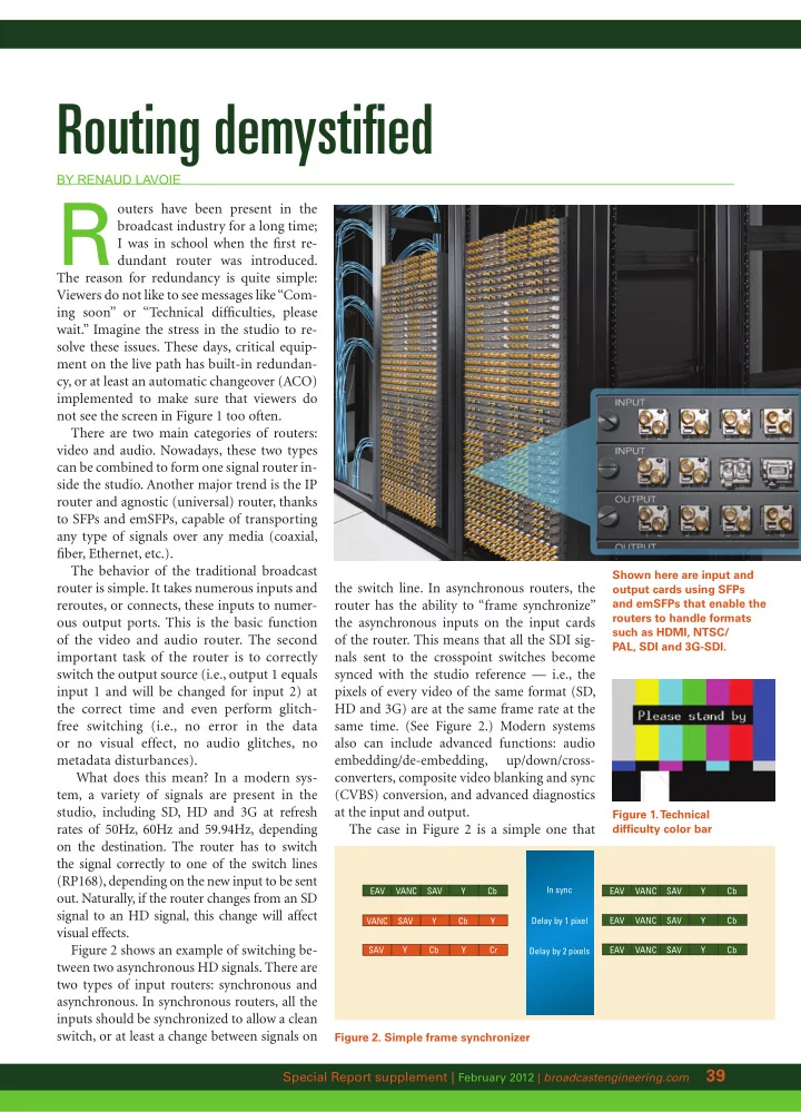
Shown here are input and
- utput cards using SFPs
and emSFPs that enable the routers to handle formats such as HDMI, NTSC/ PAL, SDI and 3G-SDI. Figure 1. T echnical difficulty color bar
EAV VANC SAV Y Cb EAV VANC SAV Y Cb EAV VANC SAV Y Cb EAV VANC SAV Y Cb In sync Delay by 1 pixel Delay by 2 pixels VANC SAV Y Y Cb SAV Y Y Cb Cr
Figure 2. Simple frame synchronizer
the switch line. In asynchronous routers, the router has the ability to “frame synchronize” the asynchronous inputs on the input cards
- f the router. This means that all the SDI sig-
nals sent to the crosspoint switches become synced with the studio reference — i.e., the pixels of every video of the same format (SD, HD and 3G) are at the same frame rate at the same time. (See Figure 2.) Modern systems also can include advanced functions: audio embedding/de-embedding, up/down/cross- converters, composite video blanking and sync (CVBS) conversion, and advanced diagnostics at the input and output. The case in Figure 2 is a simple one that