� � � � � � � � � � � � � � � � � � � � Q-circuit Tutorial Bryan Eastin, Steven T. Flammia Department of Physics and Astronomy, University of New Mexico, Albuquerque, New Mexico 87131–1156, USA Q-circuit is a list of macros that greatly simplifies the construction of quantum circuit diagrams (QCDs) in L A T EX with the help of the X -pic package. 
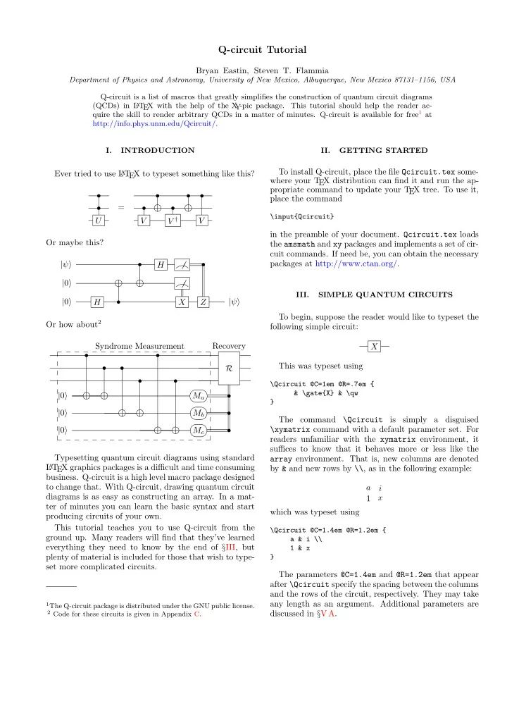
This tutorial should help the reader ac- Y quire the skill to render arbitrary QCDs in a matter of minutes. Q-circuit is available for free 1 at http://info.phys.unm.edu/Qcircuit/. I. INTRODUCTION II. GETTING STARTED To install Q-circuit, place the file Qcircuit.tex some- Ever tried to use L A T EX to typeset something like this? where your T EX distribution can find it and run the ap- propriate command to update your T EX tree. To use it, ���� ���� ���� ���� • • • • place the command = • • • \input{Qcircuit} U V V † V in the preamble of your document. Qcircuit.tex loads Or maybe this? the amsmath and xy packages and implements a set of cir- cuit commands. If need be, you can obtain the necessary �� packages at http://www.ctan.org/. | ψ � • • H � � ���� ���� ���� ���� � �� | 0 � � � � III. SIMPLE QUANTUM CIRCUITS | 0 � • | ψ � H X Z To begin, suppose the reader would like to typeset the Or how about 2 following simple circuit: Syndrome Measurement Recovery X � � � � � � � � � � � � � � � � � � • • This was typeset using • • R • • ���� ���� ���� ���� �� �� �� �� \Qcircuit @C=1em @R=.7em { & \gate{X} & \qw | 0 � M a • ���� ���� ���� ���� �� �� �� �� } | 0 � • M b ���� ���� ���� ���� �� �� �� �� The command is simply a disguised \Qcircuit \xymatrix command with a default parameter set. For | 0 � M c • readers unfamiliar with the xymatrix environment, it � � � � � � � � � � � � � � � � � � suffices to know that it behaves more or less like the Typesetting quantum circuit diagrams using standard array environment. That is, new columns are denoted L A T EX graphics packages is a difficult and time consuming by & and new rows by \\ , as in the following example: business. Q-circuit is a high level macro package designed to change that. With Q-circuit, drawing quantum circuit a i diagrams is as easy as constructing an array. In a mat- x 1 ter of minutes you can learn the basic syntax and start which was typeset using producing circuits of your own. This tutorial teaches you to use Q-circuit from the \Qcircuit @C=1.4em @R=1.2em { ground up. Many readers will find that they’ve learned a & i \\ everything they need to know by the end of § III, but 1 & x plenty of material is included for those that wish to type- } set more complicated circuits. The parameters @C=1.4em and @R=1.2em that appear after \Qcircuit specify the spacing between the columns and the rows of the circuit, respectively. They may take any length as an argument. Additional parameters are 1 The Q-circuit package is distributed under the GNU public license. 2 Code for these circuits is given in Appendix C. discussed in § V A.
2 A. Wires and gates \Qcircuit @C=1em @R=.7em { & \ctrl{1} & \targ & \qw \\ & \targ & \ctrl{-1} & \qw The command \qw draws a wire between two columns } of a QCD. The command derives its name from an ab- breviation of ‘quantum wire’. In this circuit, the command \targ draws the target gate on the wire, and the \ctrl{#1} puts a bullet down, H Z H and connects to the target which is #1 array elements below the control. Hence, to connect the second CNOT X gate properly, we used -1. A more complicated circuit with multiple controls and The diagram above was drawn using arbitrary gates might look like ���� ���� \Qcircuit @C=1em @R=.7em { • & \gate{H} & \gate{Z} & \gate{H} & \qw \\ U ���� ���� & \qw & \gate{X} & \qw & \qw • } • • • Note that \qw is used to connect a wire towards the left . which was drawn using The \gate command draws the argument of the func- tion inside a framed box and extends a wire back to the \Qcircuit @C=1em @R=.7em { previous column . When using the \gate and \qw com- & \ctrl{2} & \targ & \gate{U} & \qw \\ mands, make sure there is another column entry to the & \qw & \ctrl{-1} & \qw & \qw \\ left of the current column entry in your QCD, otherwise & \targ & \ctrl{-1} & \ctrl{-2} & \qw \\ the wire will not connect to anything (and you’ll get an & \qw & \ctrl{-1} & \qw & \qw } error), as in the following example code: In the first gate, the control bit connects to the target (**Wrong!**) on wire 3. In the second gate, each control connects to \Qcircuit @C=1em @R=.7em { the object directly above it. Finally, the third gate is an \gate{U} & \qw \\ example of how to do controls on arbitrary gates; simply \gate{U^\dag} & \qw } place the desired gate where you would normally put a target. The proper way to render this circuit would be to in- clude space for the incoming wires at the beginning by inserting the & character at the start of each new line: C. Vertical wires U Suppose we want to typeset the following circuit: U † U 1 \[ \Qcircuit @C=1em @R=.7em { • & \gate{U} & \qw \\ & \gate{U^\dag} & \qw U 2 } \] so that the middle control has to connect to more than The only difference between these two codes is that the one gate. The way to accomplish this is with the \qwx correct code has an ampersand ( & ) at the start of each command. The command \qwx[#1] takes an optional new line. input, #1 , and connects from the current position to a position #1 entries below the current position. The de- fault argument is -1. Thus, one way to typeset the above B. CNOT and other controlled single qubit gates diagram is with the following code: \Qcircuit @C=1em @R=1.2em { With just these few commands, one can already ren- & \gate{U_1} & \qw \\ der a circuit with an arbitrary number of wires and sin- & \ctrl{-1} \qwx[1] & \qw \\ gle qubit gates. In this section, we’ll learn how to draw & \gate{U_2} & \qw \\ CNOT gates and controlled single qubit gates with an } arbitrary number of controls. or, equivalently, A simple circuit with two CNOT gates in it is ���� ���� \Qcircuit @C=1em @R=1.2em { ���� ���� • & \gate{U_1} & \qw \\ & \ctrl{1} \qwx & \qw \\ • & \gate{U_2} & \qw \\ which was typeset by }
Recommend
More recommend