Processes Purpose To define the physical structuring of a system. - - PDF document

processes
SMART_READER_LITE
LIVE PREVIEW

Processes Purpose To define the physical structuring of a system. - - PDF document

Chapter 11 Processes Purpose To define the physical structuring of a system. Concepts Process architecture: A system-execution structure composed of interdependent processes. Processor: A piece of equipment that can execute a pro-


slide-1
SLIDE 1

209

Chapter 11

Processes

The process architecture brings us closer to the system’s physical level. We focus on distribution and execution, and work with processes and objects as

  • pposed to components and classes. We also deal with the physical devices

that the system will be executed on and consider whether we need to coordi- nate shared resources. This process view complements the logical structur- ing expressed in the component architecture. The process activity is structured according to two levels of abstraction. The first is the overall level, where we define the distribution of program components on the available system processors. The second level deals with the processes that structure collaboration among the objects present during

  • execution. The process activity is quickly complete if we are designing a

stand-alone administrative system. However, the complexity of process-ar- chitecture design increases significantly for monitoring and control sys-
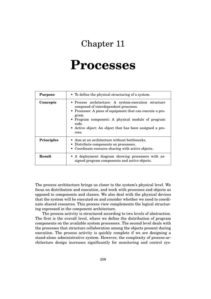
Purpose

  • To define the physical structuring of a system.

Concepts

  • Process architecture: A system-execution structure

composed of interdependent processes.

  • Processor: A piece of equipment that can execute a pro-

gram.

  • Program component: A physical module of program

code.

  • Active object: An object that has been assigned a pro-

cess. Principles

  • Aim at an architecture without bottlenecks.
  • Distribute components on processors.
  • Coordinate resource sharing with active objects.

Result

  • A deployment diagram showing processors with as-

signed program components and active objects.

slide-2
SLIDE 2

210 ________________________________________________________________Processes

tems, embedded systems, or systems with significant interactions with oth- er systems. The process activity’s result is a deployment diagram that describes the distribution and collaboration of program components and active objects on processors, as Figure 11.1 shows. In addition, you might have more detailed specifications to coordinate resource sharing, as Figure 11.9 shows for the active “Cruise control” object in Figure 11.1.

11.1 System Processes

The purpose of process architecture design is to structure execution on a physical level. This is emphasized in the following definition:

Throttle Speed-

  • meter

Figure 11.1: Deployment diagram for the Cruise Control System (Chapter 22)

: Dedicated processor «reads» Off button On button Coast button Resume button Accelerate button Brake pedal Gas pedal Clutch pedal «reads» «reads» «reads» «reads» «reads» «reads» «reads» «affects» «reads» User interface System interface Car’s other systems : Cruise control Kernel

slide-3
SLIDE 3

System Processes________________________________________________________ 211

Process architecture: A system-execution structure composed of interdependent processes. The basic unit for executing a system is the processor. We define this funda- mental concept as follows: Processor: A piece of equipment that can execute a program. An external device is a special kind of processor that cannot execute a pro- gram—at least not from our system’s point of view. Processors execute the components that arise from activity described in the previous chapter, as emphasized in this principle: Principle: Distribute components on processors. The process architecture must ensure a satisfactory system execution on the available processors, as expressed in the following principle: Principle: Aim at an architecture without bottlenecks. We can get far with the process architecture by simply designing each class and its solo operations. However, some systems are more complex because they involve concurrent processes that require coordination. A process is a collection of operations that are executed in a bounded and linked sequence. Thus, concurrent processes mean that operations from more than one such sequence are executed at the same time. Concurrency arises when a system is implemented on several proces-

  • sors. For example, a bank administration system might be executed on local

processors in each bank branch, as well as several central processors that share a database. Concurrency is also a key design issue, for example, when a mobile telephone is used to access services that are executed on other

  • computers. Even if a system is based on one processor, several concurrent

processes can share the single processor capacity. A running object-oriented system comprises a large and varying num- ber of objects. With a typical mobile telephone, there will be objects that represent all incoming and outgoing calls, as well as all address book en-

  • tries. In addition, there will be objects with active operations that imple-

ment certain monitoring functions. There will also be objects handling user- interface objects that might be present during execution, such as windows, panels, and icons. Finally, there will be objects handling the connection with the carrier’s transmission system. All in all, we have numerous objects with very different characteristics. Active objects are active during the system execution. A system’s pro- cesses and active objects are two sides of the same coin:

slide-4
SLIDE 4

212 ________________________________________________________________Processes

Active object: An object that has been assigned a process. The other kind of objects exist inside program components that constitute most of a system: Program component: A physical module of program code. No processes are assigned to program components. They are passive during execution, until one of their operations is called as part of a process execu-

  • tion. And, once the operation’s execution is complete, the program compo-

nents re-enter the passive state. Process-architecture design requires thorough knowledge of the techni- cal platform and facilities that are available for coordinating shared com- puter resources. In the process architecture, we handle this coordination task using active objects: Principle: Coordinate resource sharing with active objects. When we introduce such objects, we will select mechanisms that coordinate use of the resource in question. We can summarize the subactivities in process-architecture design as shown in Figure 11.2. We start by defining and distributing program com-

  • ponents. In this process, we can use different distribution patterns. We then

identify coordination needs by searching for resources that several process- es share. If we find such resources, we select coordination mechanisms, supported by a collection of patterns.

Identify shared resources Select coordination mechanisms

Figure 11.2: Subactivities in process-architecture design

Distribute program components Deployment diagram Class diagram and component specifications Explore coordination patterns Explore distribution patterns

slide-5
SLIDE 5

Distribute Program Components__________________________________________ 213

11.2 Distribute Program Components

Process-architecture design takes as its departure point the logical compo- nents that arise from the component activity. The aim here is to achieve a reasonable distribution of these components on the processors that are available for execution. You can delay process-architecture design until you are almost finished designing the component architecture and the individual components. The process-architecture activity can thus serve to integrate solutions you have already designed. Alternatively, you can start on the process architecture early and produce an exploratory and experimental definition of component and object properties. The activity can thus influence the design of the com- ponent architecture. Which sequence you choose depends on your strategy. In any case, you must carefully ensure consistency between component ar- chitecture, process architecture, and component design. The first step is to separate program components and active objects. To do this, you take all logical components from the component architecture. If a component contains objects with active operations, you divide the logical component into a corresponding number of active objects, which contain the active operations, and a program component, which contains the rest of the logical component. The second step in distributing components is to determine the avail- able processors. With administrative systems, you can typically accomplish this by determining which computers will be used for system execution. For example, with a company that has a main department and six geographi- cally dispersed branches, you might find a network with a powerful PC at the main department and an average PC at each branch. Thus, there are seven interconnected processors available. With a technical system, you can identify the available processors in a similar manner. The third step is to distribute the program components—which contain

  • nly passive objects—and the active objects on processors. You can use the

component architecture to derive ideas for this distribution. With a layered component architecture, a simple and typical processor architecture is to place the whole system on a single processor. This processor thus contains all of the system’s logical components. If the function component contains active functions, they are also executed by the single processor through some kind of resource sharing. With a client-server architecture, you have a lower layer containing a server for a number of clients in an upper layer. You can execute this archi- tecture on either a single or multiple processors. If you must execute on a single processor, you must examine whether your process architecture has to handle a number of clients that execute concurrently or if this is handled by an underlying system. You may, for example, have several independent user-interface objects that are clients to a server containing the function

slide-6
SLIDE 6

214 ________________________________________________________________Processes

and model components. If all of these clients are executed on the same pro- cessor and your window system is not solving the problem, then you must develop a process architecture that structures the concurrent execution of the clients and the server. It is, however, more typical to use a client-server architecture when a system is executed on several geographically dispersed processors. One ex- ample of this is The Dankort System, described in the previous chapter. One part of the system consists of a central server, with a terminal at each

  • f the associated customer locations. The terminals are clients of the cen-

tral server, and each client also has its own processor. In this case, you must define a separation between components on the server and on the clients. This separation can be based on one of the three patterns that we describe in the following section.

Example

Figure 11.3 shows the component architecture of the Cruise Control System (Chapter 22). Because we have only one processor, the distribution of com- ponents on processors is quite simple and straightforward. Figure 11.4 shows the resulting process architecture. We defined the four overall com- ponents as program components containing only passive objects. We took the dependency relations between them directly from the component archi-

Figure 11.3: Class diagram for the Cruise Control System (Chapter 22) «component» System interface «component» Other’s updates «component» Other’s readings «component» Own readings «component» Cruise control «component» Kernel «component» Car’s other systems «component» User interface

slide-7
SLIDE 7

Explore Distribution Patterns ____________________________________________ 215

  • tecture. This deployment diagram is an intermediate result; we refine it

throughout this chapter to arrive at the final solution shown in Figure 11.1.

11.3 Explore Distribution Patterns

We often face the situation wherein a system is distributed on several pro- cessors connected by a network. With administrative systems, it is becom- ing more and more common to have several computers distributed in the application domain. With embedded systems, there are typically several processors available. In both cases, you can employ a client-server architec- ture to distribute a simple logical architecture on a set of connected proces-

  • sors. In this distribution, you can use one of the following patterns.

The Centralized Pattern

The simplest solution to the distribution problem is to distribute as little as

  • possible. You can accomplish this by keeping all data on a central server

Figure 11.4: Program-component distribution on the processor in the Cruise Control System (Chapter 22)

: Dedicated processor User interface System interface Car’s other systems Kernel

slide-8
SLIDE 8

216 ________________________________________________________________Processes

and having the clients handle only the user interface. All requests and up- dates are implemented as calls from a client to the server, where the server responds by carrying out the relevant function on the model and returning potential output data to the client. Thus the whole model and all functional- ity reside on the server, and the clients basically act like simple terminals. Figure 11.5 illustrates this pattern. There are several advantages to this process architecture. You can im- plement it with inexpensive clients. All data is consistent because it exists in one place. The structure is simple to understand and implement. And, fi- nally, the network traffic is moderate.

Figure 11.5: Deployment diagram for the centralized pattern

: Server System interface Function Model User interface : Client System interface User interface

more clients

slide-9
SLIDE 9

Explore Distribution Patterns ____________________________________________ 217

The main disadvantage is low-level robustness. If the server or the net- work is down, the clients cannot do anything. Another disadvantage is that access time will be relatively high because activating any client function in- volves an exchange with the server. Finally, because data resides only in

  • ne place, the design does not facilitate backup. This problem has to be han-

dled separately. Use of this pattern requires that the problem-domain model reflect a centralized point of view.

The Distributed Pattern

The distributed pattern represents the opposite design ideal compared to the centralized pattern. Here, everything is distributed on the clients and the server is needed only to broadcast model updates between clients. A copy of the complete model resides on each of the clients. Figure 11.6 illus- trates this pattern.

Figure 11.6: Deployment diagram for the distributed pattern

: Client System interface Function Model User interface : Server System interface

more clients

slide-10
SLIDE 10

218 ________________________________________________________________Processes

A main advantage of this architecture is low access time, since the func- tions and model are on the local client and thus encounter no network traf-

  • fic. Robustness is maximized, since an individual client can continue to

work even if the network, the server, and all other clients are down. There is plenty of backup since every client has a copy of the complete model. One disadvantage is the amount of redundant data and—what is more problematic—the potential for inconsistency among data residing on differ- ent clients. There is high network traffic as updates on any client are broad- casted to all other clients. The technical requirements for clients also in- crease because they must run the model, functions, and interfaces. Finally, the architecture is more complex to understand and implement, mainly be- cause of the model distribution. Use of this pattern requires a distributed problem domain and function-

  • ality. It is particularly relevant if the model is simple and the functions are

complicated.

The Decentralized Pattern

The decentralized pattern resides somewhere in between the two previous

  • patterns. The idea is that clients own their own data, so only data that is

common to clients resides on the server. Thus, the structural design of cli- ents and server are the same. The difference is one of content: the server holds the common model and the functions on it, whereas a client holds the data belonging to its part of the application domain. Figure 11.7 illustrates this pattern. The decentralized pattern has several advantages. Data are consistent because there is no duplication among clients or between clients and server. The network load is low because the network is only used when common da- ta on the server is updated. Finally, the access time for the local data is low, though access to the common data takes longer. The main disadvantage is that all processors must be capable of execut- ing complex functions and maintaining a large model. This will increase the hardware costs. Furthermore, the system has no built-in backup facility, which would probably require local handling. This pattern is most useful if you can separate the problem domain into several similar subdomains, where each subdomain will be the application domain for a client. If this is difficult, there may be a lot of shared data that will reside on the server, which will complicate updates. In this case, you might be wise to use the centralized pattern instead.

slide-11
SLIDE 11

Identify Shared Resources________________________________________________ 219

11.4 Identify Shared Resources

Once you have distributed program components and active objects on pro- cessors, you have laid the foundation for the process architecture. The re- maining task is to identify potential bottlenecks stemming from extensive

Figure 11.7: Deployment diagram for the decentralized pattern

: Client System interface Function Model (local) User interface : Server System interface Function Model (common) User interface

more clients

slide-12
SLIDE 12

220 ________________________________________________________________Processes

  • r shared use of computer resources. Any system can have bottlenecks re-

lated to sharing the following resources:

  • Processor
  • Program component
  • External device

To identify resource sharing, you must know how classes and operations are

  • specified. Therefore, it is difficult to complete this part of process architec-

ture design before all components have been designed. However, it is usual- ly not a good idea to postpone the process activity that long. Instead, you should expect several iterations between component and process design.

Processor Sharing

Processor sharing occurs if two or more processes are executed concurrently

  • n the same processor. Your process architecture must ensure a reasonable

interplay among the objects that are present when the system is executing. Figure 11.2 outlines an interplay among five objects, each with its own set of operations that can be called by other operations. A process is a se- quential call and execution of a bounded and linked set of operations that are activated through one or more objects. In the figure, a process is illus- trated as an arrow through the operations involved. Process 1 sequentially calls operations o1 in object 1, o3 in object 2, and o5 in object 3. When opera-

Process 3 Figure 11.8: Cooperating objects Process 1 Process 2

Object 1

  • 1
  • 2
  • • •

Object 4

  • 7
  • 8
  • • •

Object 2

  • 3
  • 4
  • • •

Object 3

  • 5
  • 6
  • • •

Object 5

  • 9
  • 10
  • • •

Process 4

slide-13
SLIDE 13

Identify Shared Resources________________________________________________ 221

tion o5 is finished, process 1 returns to object 2, then to object 1, and finally to the place from which it was first activated. Each operation calls the next and there is no concurrency. Process 2 creates concurrency as it initiates both process 3 and process 4 during the execution of operation o7 in object 4. The cooperation between these two processes is simple, as they just begin and end in the same place. They share no computer resource except if both are executed on the same

  • processor. If that is the case, we must design how they share that resource.

At this point in the process activity, we have turned all logical compo- nents into program components and active objects, and we have distributed them on the avaliable processors. The program components that are defined directly from logical compo- nents must obey the dependency relations defined for the corresponding logical components. If you split logical components because of active opera- tions, you should link the resulting program components and active objects to the program components or active objects that they depend on. Such a dependency relation is drawn in the deployment diagram as a dashed line with an arrow indicating the direction of the dependency. The scenario in Figure 11.8 illustrates the guidelines above. We can as- sume that all five objects are members of classes that are defined in the same logical component. Operation o7 in object 4 is an active operation as it continues a separate process after it has activated operation o4 in object 2. Therefore, we must make object 4 an active object. The other four objects are passive and can remain in the same program component.

Program-Component Sharing

A program component is shared when two or more concurrent processes call

  • perations in that component. This kind of resource sharing can also be

seen in Figure 11.8. Assume that objects 1, 2, 3, and 5 are placed in the same program component. This program component is then shared by pro- cess 1, 3, and 4, as all three call operations in that component. We do not know from the figure how process 1 and 2 are initiated, but we know that processes 3 and 4 may call operations in the program component concur- rently. Concurrent attempts to use a shared program component occur for dif- ferent reasons. In process-architecture design, we distinguish between two different forms of concurrency:

  • true concurrency, and
  • random concurrency
slide-14
SLIDE 14

222 ________________________________________________________________Processes

True concurrency describes a situation in which two or more events in the system’s context can occur at the same time, and both require an immediate response involving the same program component. With the architectural pattern in Figure 11.5, two or more clients may call operations on the server at the same time because they need to update an event in the server’s mod- el component. In this case, the server’s system interface is the shared pro- gram component. Another example is that a user activates an operation through the user interface at the same time as a client activates one through the system interface. In this case, the server’s function component is the shared program component. Random concurrency is when two or more operations are designed to execute at the same time. We can find this in all parts of a system, and it typically occurs because we have designed the system’s functions in a way that can initiate concurrent execution of more than one operation. We might, for example, have a system with two signalling functions, each of which monitors a part of the model. In the function-component design, we have specified both functions as active operations placed in two different classes, and during execution we expect to have an object from each class. This design may be necessary. But it might also be possible to remove this concurrency by modifying the function component. In the latter case, we will denote it as random concurrency.

External-Device Sharing

An external device can be shared by two or more concurrent processes. This kind of sharing happens, for example, when several processes use the same printing device. We start by identifying the external devices that our system will ex-

  • ploit. These might be simple devices such as a button or an antenna, or they

might be more complex systems such as a measuring unit or a printer. We represent each device as an object and connect it to the program compo- nents and active objects that use it. The connection can be annotated to de- scribe the way in which the device is used. Figure 11.1 shows an example of this. On many technical platforms, the operating system handles concurren- cy problems related to external-device sharing. However, you should always ascertain whether problems originating from device sharing are solved by the operating system or whether you must handle them explicitly as a part

  • f the system’s design.

Find Potential Bottlenecks

When you have distributed components and identified shared resources, you must still face a crucial design question: Have you created bottlenecks

slide-15
SLIDE 15

Identify Shared Resources________________________________________________ 223

in the system execution? To determine this, you can answer these ques- tions:

  • What is the relationship between the capacity of each processor and

the needs of the active objects assigned to it? Which processors thereby constitute potential bottlenecks?

  • What is the accessibility, capacity, and load of the different external

devices in the interface? Which external devices thereby constitute potential bottlenecks?

  • Which parts of the model need to be stored on which storage media

and how are copies handled? What are the potential bottlenecks for data storage?

  • What is the capacity and load of the system’s connections? Which con-

nections thereby constitute potential bottlenecks? You have two options if you find essential bottlenecks. You can change the design, and thereby the distribution of components onto the available pro-

  • cessors. Or, you can change the hardware configuration by using more pro-

cessors or more powerful processors.

Example

The Dankort System, described in Chapter 10, has very significant time

  • constraints. The heart of this system is the CR80 system, which primarily

controls and registers transactions. The machinery was determined in ad- vance before the design started, and it was not particularly well suited for the task. The challenge for the designers, therefore, was to attain the desired speed despite the machine’s limited capacity. They solved the design task by putting the system’s data storage on a disk cache and splitting the card da- tabase into two parts executing on separate processors to enable two con- current requests. In this example, a simple distribution of the card data- base on one processor was extended with two extra processors and a new system decomposition. Thus, as this example shows, we might have to re- consider the component architecture during process architecture design.

Example

With the cruise control system, we can easily identify one kind of resource

  • sharing. The system-interface and user-interface components both handle

events in the system’s context, and these events can occur concurrently. The system is executed on a single processor, and the two components can re- quest this resource at the same time.

slide-16
SLIDE 16

224 ________________________________________________________________Processes

A second kind of resource sharing occurs because both the system-inter- face and the user-interface component access the the kernel component, which is thereby a shared program component. A closer look at class operations in the system reveals a third kind of re- source sharing. In Chapter 22, we described how we arrived at an active op- eration “regulate speed.” This operation is assigned to a class, “Cruise con- trol,” and during execution there is one object from this class. These ele- ments are moved out of the “Kernel” program component, which contains the rest of the original, logical kernel component. Given this, the project re- quires coordination and handling of concurrency.

11.5 Select Coordination Mechanisms

If you identify a need to coordinate resource sharing, you must select a rele- vant coordination mechanism. We can illustrate the use of coordination mechanisms using the scenar- io in Figure 11.8. Process 3 calls operation o4 in object 2, and process 4 calls

  • peration o10 in object 5. If we want to be able to do that concurrently on a

single processor, we need a mechanism to coordinate the sharing of that processor. Process 1 and process 3 can both activate an operation in object 2. If we want these processes to be concurrent, a conflict could occur because object 2 is unable to serve them both at the same time. That would be the case, for example, if operation o3 and o4 are accessing the same attributes. Process-architecture design is highly dependent upon the technical

  • platform. You might find yourself in a situation in which you have several

active objects, and thereby have a fundamental need to coordinate concur- rent processes. This is, however, not a major problem if the technical plat- form offers a sufficient number of processors and facilities for coordination. Coordination mechanisms are available in various ways and combina- tions in different programming languages and technical platforms. Given this variety, it is difficult to provide general guidelines for solving a coordi- nation problem. In general, we suggest that you coordinate resource shar- ing by means of an active object. So, if a resource is shared, you can intro- duce an active object to handle potential conflicts. This idea effectively en- capsulates the design problem and thereby achieves a very robust architec- ture, in accordance with the general criteria for object-oriented design. The active object that encapsulates the problem requires that you select a rele- vant mechanism. In the following section, we provide four patterns for such a coordination mechanism.

slide-17
SLIDE 17

Explore Coordination Patterns____________________________________________ 225

11.6 Explore Coordination Patterns

Basically, you can coordinate resource sharing among concurrent processes using two different mechanisms: synchronization and data exchange. With synchronization, one process waits for another. Thus, at the time of syn- chronization, the system knows the state of both processes. With data ex- change, data is transferred from one process to another without assuming any synchronization. When you are selecting a coordination mechanism for an active object to guard a shared resource, it is useful to look at four patterns:

  • dedicated monitor,
  • centralized task dispatcher,
  • subscription to state changes, and
  • asynchronous data exchange.

A dedicated monitor ensures atomic access to shared resources. The moni- tor’s operations ensure that only one process can execute at a time. A moni- tor can, for example, encapsulate a printer so that the print operation can- not be activated by a process if it has already been activated by another

  • process. If it is in use at activation, the calling process waits for it to finish

before access is granted. This waiting period is transparent to the calling

  • bject. The risk of this pattern is that you can construct it so that there is a

long waiting time in which the calling process cannot get free. The centralized task dispatcher gathers the control of the system’s exe- cution in a single active object. This object is the task dispatcher, which

  • nly allows processes to move into shared areas under certain conditions.

The problem with this mechanism is that control is centralized. The task dispatcher can also become very complex. The advantage is that the activa- tion of operations can be distributed as needed after an overall evaluation

  • f priorities.

A special case of the task dispatcher is the event loop, which is used on several technical platforms. An event loop is designed with program state- ments that continuously check to see if anything has happened that re- quires a response. If, for example, you need to control both a keyboard and a mouse, you might choose an event loop and continuously check if a key was pressed or the mouse was moved. This pattern requires that the event loop is executed fast enough to catch all the events that should be checked. You can select subscribing to state changes when designing the control

  • f a system with active operations that, for example, realize signaling func-
  • tions. The operation continuously compares the state of a part of the mod-

el’s objects with a specified acceptable state space. If the problem domain changes beyond this state space, the operation gives an alarm. As we have

slide-18
SLIDE 18

226 ________________________________________________________________Processes

already seen, you can provide the function with an independent process. However, you can avoid this if you equip the relevant part of the model with a corresponding data structure to handle subscriptions. You then activate the subscriptions one by one each time certain model events occur. Asynchronous data exchange assumes that the technical platform has buffers in the form of protected data storage of files with atomic access. If the buffers are big enough, the processes can coordinate by exchanging larger amounts of data without the need to synchronize. We can, for exam- ple, imagine a currency system with two processes: one continuously re- ceives currency rates from currency exchanges; the other performs complex calculations, then presents selected currencies in a graph. The first process must be able to get rid of its data at high speed. The other process only reads every once in a while, but it removes large portions of outdated data each time.

Example

With the cruise control system, we have three kinds of resource sharing. One solution is to use the centralized-task-dispatcher pattern. The dis- patcher can use an event loop to control the execution of the interface com-

  • ponents. In addition, this loop can provide processing time to the function

that regulates the car’s speed. This solution only requires that the proces- sor is powerful enough to ensure that no events are lost. Figure 11.1 shows the resulting process-architecture design; Figure 11.9 shows the details of the active object.

Figure 11.9: Outline of the dispatcher loop in the cruise control object loop for all pedal objects in the system interface update the model’s car object; for all button objects in the user interface update memory object; update state; if state = switched on then read speedometer; update speed in the model’s car object; if state = active then regulate speed; end

slide-19
SLIDE 19

Principles_______________________________________________________________ 227

11.7 Principles

In this chapter, we discussed process-architecture design. Our guidelines for this activity are summarized in the following principles: Aim at an architecture without bottlenecks. The system’s processes will exploit the technical platform’s resources. This necessitates an eval- uation of the system’s potential bottlenecks. Distribute components on processors. The logical components defined during component design are distributed on the available processors. The result of this is a collection of mutually dependent program com- ponents and active objects. Coordinate resource sharing with active objects. With several concurrent processes, you must design how system resource sharing will be coor-

  • dinated. Some coordination problems can be solved using synchroni-

zation facilities in the technical platform. In other cases, you can use general patterns to outline coordination mechanisms.

11.8 Exercises

Review Questions

1. What is a processor? 2. What is a process? 3. What is the purpose of the process architecture? 4. What is an active object? 5. What are the characteristic features of the centralized pattern for component distribution? 6. What are the characteristic features of the distributed pattern for component distribution? 7. What are the characteristic features of the decentralized pattern for component distribution? 8. Which types of resources can be shared? 9. Which patterns can be used to coordinate resource sharing? 10. Where should we look for potential bottlenecks? 11. How is the process architecture specified?

Problems

12. Describe how concurrency might occur for the architecture outlined in Figure 11.4. Discuss ideas for solving this problem.

slide-20
SLIDE 20

228 ________________________________________________________________Processes

13. Consider a well-known distributed system with a client-server archi-

  • tecture. Make an outline of the process architecture and evaluate its

qualities. 14. Video rental store. Continue your consideration of the system for man- aging customers and their rentals in a video rental store (see Exercise 3.13). The system will be implemented with a shared database and several PCs in a local area network. Design a process architecture and provide arguments for your choices. 15. Mobile phone. Continue your consideration of the system for a simple mobile phone (see Exercise 3.14). Design a process architecture and provide arguments for your choices. 16. Teaching administration. Continue your consideration of the system for monitoring student activities in a university department (see Exer- cise 3.15). The system is implemented with a shared database and must be accessible from all work stations in the department. Design a process architecture and provide arguments for your choices. 17. Elevator control. Continue your consideration of the system to control elevator movement in a building (see Exercise 3.16). Design a process architecture and provide arguments for your choices.

11.9 Literature

Process-architecture design brings us closer to the physical level. It is therefore difficult to strike an appropriate balance between considerations for design and matters related purely to implementation. This is also re- flected in the object-oriented literature. Some authors almost ignore the problems related to the system’s processes, or they provide an unreasonably simple solution to this complex problem. This is true, for example, in Coad & Yourdon (1991b). Other authors introduce all the relevant concepts and problems, making the presentation difficult to use in practice. This is true, for example, in Booch et al. (1999). We have attempted to focus on the essential design issues and avoid concrete considerations about implementation and use of special program- ming languages or facilities. However, concurrent processes easily lead to very complex problems. We would, therefore, advise you to consult litera- ture related more closely to implementation in your future work with pro- cess architectures. We recommend studying Booch et al. (1999). The notion of using a control thread to describe coordination needs ap- pears often in object-oriented literature. We use the related concept of ac- tive object. Our presentation is inspired by Booch (1994) and Rumbaugh et

  • al. (1991).
slide-21
SLIDE 21

Literature ______________________________________________________________ 229

The idea of coordinating objects can be traced back to the idea of com- municating sequential processes, first formulated by Hoare as a frame for thinking about operating-system design. Jackson (1983) is based on this role model, which is available in a newer presentation in Hoare (1985). A general treatment of the problems of coordinating concurrent processes along with various possible solutions is found in Ben-Ari (1982). Brinch Hansen (1977) can still be recommended as a good and systematic book about this subject. Finally, Gamma et al. (1995) provides a broad presenta- tion of design patterns, including patterns for coordination.

slide-22
SLIDE 22

230 ________________________________________________________________Processes