
SLIDE 1
PUP
GROUP 7
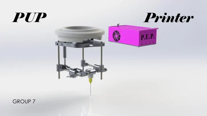
Printer GROUP 7 The Team Jack Ruskell William Meldrum- Chris - - PowerPoint PPT Presentation
PUP Printer GROUP 7 The Team Jack Ruskell William Meldrum- Chris Magnus Thush Amir Mettawa Duc Nguyen Ryan Garcia Mounts to Nikon Eclipse Ti Number of methods to mount concept must be >=1 Only one method of mounting print head to
GROUP 7
Jack Ruskell Duc Nguyen Chris Magnus William Meldrum- Thush Ryan Garcia Amir Mettawa
Mounts to Nikon Eclipse Ti microscope turret Primary structure must fit within 100 mm cube 200 g maximum weight Linear accuracy <= 1 cell diameter Speed of ~1 µm/s, slower is better Print extents of single well on 96 well plate Motion transmitted to printer from remote source Capable of printing experimentally relevant feature sizes Maximum sale price of $4,000 5-year life with 8 hours of usage per workday Minimum flowrate capable of printing experimentally relevant features In center of travel, X and Y travel directions must be aligned with optical axis and constrain needle within 1° of horizontal Printer must deposit and extract material Must print fluid with viscosity
Pa Tip must be disposable or reliably sterilized Can’t generate bio-reactive or metallic debris Sterilization with common laboratory methods System assembly/disassembly by lab technician Operation in BSL-1 clean-room environment Holding/dispensing fluid will not kill cells Number of methods to mount concept must be >=1 Size of print structure must be less than 100 mm on each side XY motion must have a 100 mm2 travel area Device weight must be less than 200 g Positional accuracy must be less than 15 µm Print speed must be ~1 µm/s Young’s modulus of component connected to the motor must be ~1.8 Gpa Inner diameter of printing tip >=2.693 mm (10 gauge needle) Keep BOM total cost under $4000 Life cycle of at least 10,400 hours for all printer components Device must print 160 µL/sec at 400 µm feature diameter Mounting to microscope must be perpendicular to vertical within ±1° and mounting to microscope must be within ±0.5°
Time to switch from extracting to depositing fluid should be >1 min Yield stress of fluid extraction tip must be >40 Pa Steps to replace or clean fluid extraction tip should be <=4 Motors rated ISO 85731 class 1/3 oil free/dry, filtered at 1 µm Components must withstand at least 3 lab cleaning chemicals Percent complex parts in device must be less than 50% Printer should meet all 8 BSL-1 requirements Dispensing mechanism can not change fluid temperature >1°C Device to be controlled via Smoothieboard 5x Bio-printer must have 5 or less motors to be controlled
Turret Mount Motor/Driving System Dispensing Mechanism Z Motion XY Motion
Only one method of mounting print head to turret mount. Print structure is 84x79x92 mm. XY motion travel area is 306 mm2. Device weight must be less than 200 g, lighter is better Positional accuracy must be less than 15 µm, smaller is better Print head travel speed is between 1.544 mm/sec. Motors are located far away from print head and microscope turret mount. Inner diameter of printing tip is 1.067 mm (17-gauge needle). Total cost of bio-printer is $3200. Life cycle of all components allows for at least five years of operation. Device prints 1 µL/sec at a feature diameter of 332 µm. Because of simplicity of print head and relatively small tolerances on components, these angular tolerances were achieved. Switch from deposition to extraction only requires a different voltage to be supplied to the linear actuators. 304 stainless steel has a yield stress of 215 Mpa. Fluid extraction tip can be pulled out of holder and replaced. Motors are dry, oil free, and enclosed to prevent debris. All bio-printer components can be cleaned with propylene, ethanol, and autoclave devices Less than 8% of components are complex. Printer will not generate large debris particles as linear actuator motors are enclosed, and material selection prevents significant wear of materials. Bio-fluid is contained only in end of dispensing mechanism line far away from components which generate heat. Bio-printer has four linear actuators to control all functions.
Subsystems
commonplace around the world.
laboratories have them
microscopes are little and expensive!
condenser port adapter is modified to hold the dispencing structure
controlled, reducing risk from supplier
located between linear rails
moment
"racking"
allows for the quick replacement of syringe
needed
ABS
to DIN rail
assembly
designed for ease of manufacturing
professional appearance
Dispensing:
Bernoulli equation
neglected
𝑄
1 = 1
2 𝜍𝑊
2 2 + 𝜍∆𝑨
2𝐵2
1 = F𝐵1
𝐺
𝑠𝑓𝑟 = 𝜍𝐵1𝑅2 + 2𝜍𝐵1𝐵2 2∆𝑨
2𝐵2
2
Motion:
𝑒 = 4 𝑅 𝜌 𝑤𝑜
no load
mm/sec
𝑤2 = 𝐵1 𝐵2 𝑤1 𝑤2,𝑛𝑏𝑦 = 0.161 𝑛𝑛2 0.172 𝑛𝑛2 ∙ 15 𝑛𝑛 𝑡 = 14.5 𝑛𝑛 𝑡
Control Box:
area, conservative approximation
OTS Parts Raw Material Manufactuirng Cost Assembly Cost $1,909.33 $284.44 $1,006.23 $320 Total: $3,520
custom part
tolerances and required operations
BEST BANG FOR YOUR BUCK MINIMAL ASSEMBLY TOOLS DESIGNED FOR FAST MANUFACTURING MANY REPEATED PARTS HIGH % OTS
Thank you, Northrop-Grumman and Cummins, for your continued support of the Capstone program and for helping make our program