PREDICTION OF MECHANICAL PROPERTIES OF CARBON - - PDF document

prediction of mechanical properties of carbon nanotube
SMART_READER_LITE
LIVE PREVIEW

PREDICTION OF MECHANICAL PROPERTIES OF CARBON - - PDF document

18 TH INTERNATIONAL CONFERENCE ON COMPOSITE MATERIALS PREDICTION OF MECHANICAL PROPERTIES OF CARBON NANOTUBE/POLYVINYLIDENE FLUORIDE COMPOSITES BY HANSEN SOLUBILITY PARAMETERS METHOD J. Ma, R. M. Larsen* Department of Mechanical and


slide-1
SLIDE 1

18TH INTERNATIONAL CONFERENCE ON COMPOSITE MATERIALS

1 Introduction In this work, Hansen solubility parameters [1] (HSP) are introduced to predict the physical properties of filler-matrix composite system. This highly efficient and economical method could be potentially applied in both control and guiding of composites processing. Excellent mechanical properties of carbon nanotubes (CNTs) enable them an excellent choice of reinforcement material for polymeric composites [2, 3]. However, due to the high aspect ratio, CNTs tend to form agglomerates, which cause the dispersion of carbon nanotubes in polymer matrix a big challenge. In order to obtain good nanotube dispersion, many methods have been tried, among which modification

  • f the CNTs and ultrasonic dispersion are widely

used [4-6]. Normally the dispersion state of the nanotubes in the polymer is evaluated after the whole composite fabrication process is completed. However, using Hansen solubility parameters (HSP) could help predicting the dispersion state of the CNTs in polymer before fabricating the composites. In this study, the mechanical properties of carbon nanotube / Polyvinylidene Flouride (PVDF) are

  • investigated. Equal amount of purified single walled

carbon nanotubes (SWNTs), nitric acid treated SWNTs, octadecylamine (ODA) modified SWNTs and multi-walled carbon nanotubes (MWNTs) blends with piezoelectric polymer PVDF have been prepared by using dimethylformamide (DMF) solution blending and injection molding method. The HSP of the various carbon nanotubes have been determined in order to predict the physical affinities between the PVDF and the various CNTs. The dispersion state of nanotubes in PVDF matrix was

  • bserved by light optical microscopy (LOM) and

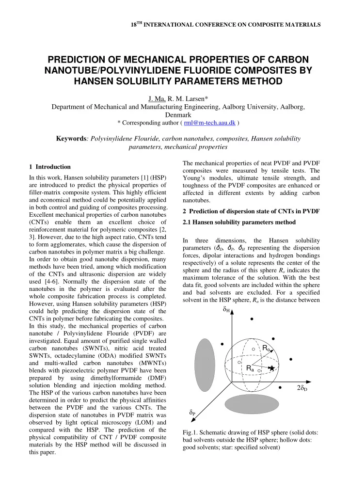
compared with the HSP. The prediction of the physical compatibility of CNT / PVDF composite materials by the HSP method will be discussed in this paper. The mechanical properties of neat PVDF and PVDF composites were measured by tensile tests. The Young’s modules, ultimate tensile strength, and toughness of the PVDF composites are enhanced or affected in different extents by adding carbon nanotubes. 2 Prediction of dispersion state of CNTs in PVDF 2.1 Hansen solubility parameters method In three dimensions, the Hansen solubility parameters (δD, δP, δH representing the dispersion forces, dipolar interactions and hydrogen bondings respectively) of a solute represents the center of the sphere and the radius of this sphere Ro indicates the maximum tolerance of the solution. With the best data fit, good solvents are included within the sphere and bad solvents are excluded. For a specified solvent in the HSP sphere, Ra is the distance between

Ro 2δD δH δP Ra

Fig.1. Schematic drawing of HSP sphere (solid dots: bad solvents outside the HSP sphere; hollow dots: good solvents; star: specified solvent)

PREDICTION OF MECHANICAL PROPERTIES OF CARBON NANOTUBE/POLYVINYLIDENE FLUORIDE COMPOSITES BY HANSEN SOLUBILITY PARAMETERS METHOD

  • J. Ma, R. M. Larsen*

Department of Mechanical and Manufacturing Engineering, Aalborg University, Aalborg, Denmark

* Corresponding author ( rml@m-tech.aau.dk )

Keywords: Polyvinylidene Flouride, carbon nanotubes, composites, Hansen solubility parameters, mechanical properties

slide-2
SLIDE 2

Table 1. Solubility and RED values of CNT in various solvents

Solvents δD

a

δP

a

δH

a

δT Purified SWNTs HNO3 SWNTs ODA SWNTs MWNT Sb RED S b RED Sb RED S b RED Methanol 15.1 12.3 22.3 29.6 1 1.01 1 0.93 5.99 1.92 Ethanol 15.8 8.8 19.4 26.5 1 0.68 1 0.84 4.53 1.37 2-propanol 15.8 6.1 16.4 23.5 0.62 1 0.93 3.34 1.00 Acetone 15.5 10.4 7 19.9 1.06 1 0.89 2.20 1.40 Tetrahydrofuran 16.8 5.6 8 19.4 1 0.84 1.21 1 0.46 1 0.81 Cyclohexanone 17.8 6.3 5.1 19.6 1.00 1.44 1.04 1.00 Ethyl acetate 15.8 5.3 7.2 18.2 1 1.01 1.24 1 0.83 1.01 Acetonitrile 15.3 18 6.1 24.4 1.44 1 1.00 4.72 1.99 N,N-dimethylformamide 17.4 13.7 11.3 24.8 1 0.74 1 0.58 3.42 1 1.40 N,N-Diethylethenamine 14.6 3.7 1.9 15.2 1.53 1.78 2.43 1 1.39 Dicloromethan, methylenchlorid 18.2 6.3 6.1 20.3 0.90 1.40 1.06 0.88 Chloroform 17.8 3.1 5.7 19 1 1.03 1.64 1 0.92 1 0.83 Tetrachloromethane 17.8 0.6 17.8 1.54 2.24 2.81 1.44 Hexane 14.9 14.9 1.75 2.22 3.25 1.77 Decahydronaphthalene 18.8 18.8 1.57 2.35 3.18 1.49 Benzene 18.4 2 18.6 1.42 2.18 2.57 1.26 Xylol, 1,2-dimethylbenzene 17.8 1 3.1 18 1.31 1.98 1.95 1.13

The HSP are in units of MPa1/2

a Refs.[7, 8] b S represent the solubility. “1” and “0” stand for the good and bad solvent, respectively.

(a) (c) (b) (d) Fig 2. The HSP sphere of different CNT (solid dots: bad solvents; hollow dots: good solvents; star: PVDF) (a) Purified SWNTs; (b) HNO3 modified SWNTs; (c) ODA modified SWNTs; (d) MWNT in solvents

10 15 20 25 30 10 20 30 5 10 15 20 25 30

D P H

10 15 20 25 30 10 20 30 5 10 15 20 25 30

D P H

10 15 20 25 30 10 20 30 5 10 15 20 25 30

D P H

10 15 20 25 30 10 20 30 5 10 15 20 25 30

D P H

slide-3
SLIDE 3

18TH INTERNATIONAL CONFERENCE ON COMPOSITE MATERIALS

the solvent and the center of the solute sphere. The schematic drawing of HSP sphere is shown in Fig.1. The ratio of Ra and Ro are described as relative energy difference (RED) value: RED=Ra/Ro (1) A perfect solvent has a RED value of 0. The RED of good solvents are normally less than 1.0 and bad solvents larger than 1.0. From the RED values and the HSP spheres of the two materials, the physical affinities between a PVDF matrix and various CNTs could be predicted. In this study, HSP of various CNTs and PVDF were determined based on a set of solubility experiments. Very small amount of CNT was added into different solvents with known HSP and sonicated for 24 hours, hereafter the determination was made on the

  • bservation of the solubility after sonication.

In Table 1, the solubility of each CNT in various solvents is displayed and RED values are calculated. DMF was chosen as the solvent in the composite process, as PVDF is soluble in it. At the same time, DMF is good solvent for purified SWNTs, HNO3 modified SWNTs and MWNT, but not for ODA modified SWNTs. Figure 2 and Table 2 illustrate the distance between the HSP sphere for the CNT and the PVDF; the RED values are calculated with respect to PVDF. The results indicate that the nitric acid treated SWNT have the best physical surface affinities with PVDF. The purified SWNT shows lower physical affinities, while MWNT and the ODA functionalized SWNT possess higher RED values and the further distance

  • f CNT sphere and PVDF matrix, so they may have

worse physical affinities with PVDF. Table 2. HSP, and Ro of various CNTs and PVDF

Material δD δP δH Ro REDb Purified SWNTs 19.4 10.3 15.0 11.1 1.35 HNO3-SWNTs 15.2 14.0 14.1 9.0 1.07 ODA-SWNTs 17.0 4.7 7.1 2.9 1.73 MWNT 18.9 2.4 12.2 8.4 2.19 PVDFa 17.1 12.6 10.6 5.0

a Calculated using published data in [9] b The RED of CNTs are calculated with respect to PVDF

Based on the above results, the HNO3 modified SWNT and purified SWNT might disperse well in the composite due to the good solubility in DMF solvent and good physical affinity with PVDF. As

  • pposed to this, due to its insolubility in DMF and

poor compatibility with PVDF, the ODA modified SWNT might disperse badly in composite. MWNTs is dispersed well in DMF but have poor compatibility with PVDF, such that the dispersion in PVDF composites might be in between HNO3 modified SWNTs and ODA modified SWNTs. 2.2 Dispersion state The dispersion state of the CNTs in PVDF composites were characterized by LOM (light

  • ptical microscopy) and compared with the

predicted results obtained by HSP method. Figure 3 exhibits the LOM images of various CNT/PVDF composite films. The dispersion of purified SWNT, HNO3 modified SWNT and MWNT were good in the PVDF, no obvious agglomerations of CNTs were observed in Fig.3 (a)(b)(d), while the ODA modified SWNTs were dispersed badly in the PVDF composites and lots of agglomerates were observed from the image Fig.3 (c). These observations agree very well with the prediction by using Hansen solubility parameters method. The dispersion of CNTs in polymer matrix was largely influenced by the solubility of CNTs in solvent, secondly influenced by the surface physical affinities of the polymer matrix and the CNT fillers.

  • Fig. 3. The LOM images of CNTs in PVDF, (a)

Purified SWNTs; (b) HNO3 treated SWNTs; (c) ODA modified SWNTS; (d) MWNTs

slide-4
SLIDE 4

3 Mechanical properties Several researchers have

  • bserved

that the mechanical properties of the nano-composites are affected by the dispersion of the CNTs in polymer [10, 11]. The achieved mechanical properties in terms of Young’s modulus, ultimate tensile strength, toughness, failure strain and respective standard deviation of PVDF and the composites with 1wt% nanotubes are listed in Table 3. The Young’s modulus was calculated according to ISO527-1. The neat PVDF samples fabricated with the same procedure with DMF as the solvent and molded by injection molding and have a Young’s modulus of 1.138± 0.101GPa and strength of 41.84± 0.85MPa. All the SWNTs filled PVDF composites lead to higher Young’s modulus than the original

  • PVDF. The Young’s modulus improvement of the

purified SWNTs and MWNT filled PVDF composites are the best. However, it seems that the measured Young’s modulus does not come close to the Young’s modulus predicted by the rule of mixture [12, 13] in any of the samples. Addition of MWNT improves the ultimate tensile strength despite the apparently poor physical affinity with the

  • PVDF. However, addition of SWNT does not

improve the ultimate tensile strength. Despite good dispersion of the purified SWNTs and HNO3 modified SWNTs as well as MWNTs, the Young’s modulus show little improvement and tensile strength is close to pure PVDF. The poor mechanical properties could be due to poor debundling of the carbon nanotubes. Toughness and failure strain are deteriorated by adding CNTs in PVDF. The composites with ODA functionalized nanotubes have the lowest toughness and failure stain only at 10.37± 1.40 J/m3 and 28.92 ± 3.98%. The ODA functionalized SWNTs are poorly wetted by PVDF, and form lots of

  • agglomerates. The poor physical affinity also results

in an interface with low strength, reducing the mechanical performance of the composite. Many other researchers have found that the surface functionalization of SWNTs could improve the mechanical properties of composites [14-17]. In our study, it was found that the properties of the composites are affected by the modification mainly because the modification affects the dispersion of

  • CNTs. And the above observations indicate that the

dispersion state of the filler in matrix affect the mechanical properties of composites. Despite the difficulties, the effort to increase the dispersion and thus the mechanical properties would be interesting. The application of HSP method to predict the dispersion of CNTs in polymers needs to be developed and discussed more in the future. Table 3. Mechanical properties from Tensile Testing at room temperature for PVDF and SWNT/PVDF composites

Composite type Young’s modulus (GPa) Ultimate tensile strength (MPa) Toughness (J/m3) Failure strain(%) Neat PVDF 1.138 ± 0.101 41.84 ± 0.85 12.34 ± 2.94 34.48 ± 7.51 1 wt% purified SWNT/PVDF 1.264 ± 0.028 41.28 ± 0.97 11.73 ± 1.05 32.34 ± 2.79 1 wt% HNO3- SWNT/PVDT 1.180 ± 0.004 41.07 ± 0.09 10.81 ± 1.81 29.76 ± 4.92 1 wt% ODA- SWNT/PVDF 1.167 ± 0.003 40.70 ± 0.17 10.37 ± 1.40 28.92 ± 3.98 1wt% MWNT/PVDF 1.242 ± 0.009 43.15 ± 0.14 11.38 ± 0.29 30.56 ± 0.64

  • 4. Conclusion

Hansen solubility parameters could help selecting solvent for composites processing, and predict the dispersion state of SWNTs in PVDF polymer matrix. Purified and HNO3 functionalized SWNTs dispersed well in PVDF, while ODA functionalized dispersed badly, which were in agreement with the compatibility predicted by Hansen solubility parameters. The better mechanical properties are related to better

  • dispersion. The Young’s modulus of PVDF was

improved by adding SWNTs, the purified SWNT/PVDF shows the largest Young’s modulus, the MWNT/PVDF is the strongest, the toughness of the PVDF composites isn’t improved by adding CNT, ODA functionalized SWNTs composites exhibit the poorest mechanical properties due to the agglomeration of the SWNTs in PVDF. References

[1]

  • C. M. Hansen, Hansen solubility parameters : a

user's handbook, Boca Raton, Fla.: CRC Press, 2000. [2]

  • M. D. Frogley, D. Ravich, and H. D. Wagner,

“Mechanical properties of carbon nanoparticle- reinforced elastomers,” Composites Science and

slide-5
SLIDE 5

5 PREDICTION OF MECHANICAL PROPERTIES OF CARBON NANOTUBE/POLYVINYLIDENE FLUORIDE COMPOSITES BY HANSEN SOLUBILITY PARAMETERS METHOD Technology, vol. 63, no. 11, pp. 1647-1654, Aug, 2003. [3]

  • S. S. Xie, W. Z. Li, Z. W. Pan et al.,

“Mechanical and physical properties on carbon nanotube,” Journal of Physics and Chemistry of Solids, vol. 61, no. 7, pp. 1153-1158, Jul, 2000. [4]

  • A. Curulli, S. N. Cesaro, A. Coppe et al.,

“Functionalization and dissolution of single- walled carbon nanotubes by chemical-physical and electrochemical treatments,” Microchimica Acta, vol. 152, no. 3-4, pp. 225-232, Jan, 2006. [5]

  • D. Tasis, N. Tagmatarchis, V. Georgakilas et al.,

“Soluble carbon nanotubes,” Chemistry-a European Journal, vol. 9, no. 17, pp. 4001-4008, Sep 5, 2003. [6]

  • R. Larsen, “Modification of single-walled carbon

nanotubes and its influence on the interfacial strength in polymeric composites,” Journal of Materials Science, vol. 44, no. 3, pp. 799-807, Feb, 2009. [7]

  • C. M. Hansen, Hansen solubility parameters : a

user's handbook, 2nd ed., Boca Raton: CRC Press, 2007. [8]

  • A. F. M. Barton, CRC handbook of solubility

parameters and other cohesion parameters, 2nd ed., Boca Raton: CRC Press, 1991. [9]

  • A. Bottino, G. Capannelli, S. Munari et al.,

“Solubility Parameters

  • f

Poly(Vinylidene Fluoride),” Journal of Polymer Science Part B- Polymer Physics, vol. 26, no. 4, pp. 785-794, Apr, 1988. [10]

  • R. Andrews, D. Jacques, A. M. Rao et al.,

“Nanotube composite carbon fibers,” Applied Physics Letters, vol. 75, no. 9, pp. 1329-1331, Aug 30, 1999. [11]

  • Y. S. Song, and J. R. Youn, “Influence of

dispersion states of carbon nanotubes on physical properties of epoxy nanocomposites,” Carbon,

  • vol. 43, no. 7, pp. 1378-1385, Jun, 2005.

[12]

  • S. W. Tsai, and H. T. Hahn, “Role of Interface in

the Strength of Composite-Materials,” Abstracts

  • f Papers of the American Chemical Society, no.
  • pp. 108-108, Apr,1979.

[13]

  • H. L. Cox, “The Elasticity and Strength of Paper

and Other Fibrous Materials,” British Journal of Applied Physics, vol. 3, no. pp. 72-79, Mar,1952. [14]

  • Y. Breton, J. P. Salvetat, G. Desarmot et al.,

“Modifications

  • f

nanotubes surface and microtexture influence

  • n

MWNTS-based composites properties,” Structural and Electronic Properties

  • f

Molecular Nanostructures, vol. 633, pp. 574-578,635, 2002. [15]

  • J. Zhu, J. D. Kim, H. Q. Peng et al., “Improving

the dispersion and integration of single-walled carbon nanotubes in epoxy composites through functionalization,” Nano Letters, vol. 3, no. 8, pp. 1107-1113, Aug, 2003. [16]

  • D. Blond, V. Barron, M. Ruether et al.,

“Enhancement

  • f

modulus, strength, and toughness in poly(methyl methacrylate)-based composites by the incorporation of poly(methyl methacrylate)-functionalized nanotubes,” Advanced Functional Materials, vol. 16, no. 12,

  • pp. 1608-1614, Aug 4, 2006.

[17]

  • J. N. Coleman, U. Khan, W. J. Blau et al.,

“Small but strong: A review of the mechanical properties

  • f

carbon nanotube-polymer composites,” Carbon, vol. 44, no. 9, pp. 1624- 1652, Aug, 2006.