
SLIDE 1
POWER COUPLERS FOR
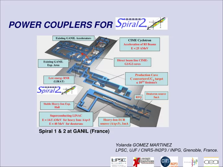
Spiral 1 & 2 at GANIL (France)
Yolanda GOMEZ MARTINEZ LPSC, UJF / CNRS-IN2P3 / INPG, Grenoble, France.
POWER COUPLERS FOR Spiral 1 & 2 at GANIL (France) Yolanda GOMEZ - - PowerPoint PPT Presentation
POWER COUPLERS FOR Spiral 1 & 2 at GANIL (France) Yolanda GOMEZ MARTINEZ LPSC, UJF / CNRS-IN2P3 / INPG, Grenoble, France. Outline Spiral 2 couplers layout & parameters Tests Mechanical test Radiofrequency (RF) tests Coupler
Yolanda GOMEZ MARTINEZ LPSC, UJF / CNRS-IN2P3 / INPG, Grenoble, France.
SRF 2011. Michigan. Juillet 29th, 2011
SRF 2011. Michigan. Juillet 29th, 2011
Parameters Values Number 26 (12 + 7*2) Frequency 88.05 MHz Nominal power* 10 kW CW Power during test Up to 40 kW CW S11 < -25 dB Thermal load at 4.2 K < 1 watt Accepted reflected power 100% Qext at nominal current* 1.3 106
*Spiral 2 nominal accelerating gradient 6.5 MV/m *Spiral 2 nominal current. 5 mA deuterons
35 m
SRF 2011. Michigan. Juillet 29th, 2011
SRF 2011. Michigan. Juillet 29th, 2011
Temperatures in a cryomodule β = 0.07
SRF 2011. Michigan. Juillet 29th, 2011
CAEN PARIS GRENOBLE
Upgrades Without With Hollow antenna with an internal clamp [to be far from the 50 Hz frequency (EU electrical network frequency) and to avoid plastic deformation of the antenna] f1 = f2 = 59 Hz f1 = f2 = 73.5 Hz Acceleration max 10 g support to the CF40 flange. [to avoid the deformation of the flange] Accelerationmax: 4g to get 70 MPa Acceleration max : 8g to get 70 MPa
~ 600 km
internal support Фhole: 10 mm Фantenna: 15.5 mm 0.65 mm ~ 400 mm
First mode
SRF 2011. Michigan. Juillet 29th, 2011
SRF 2011. Michigan. Juillet 29th, 2011
Multipactor and power of an uncoated , a 1 nm TiN and 30 nm TiN coated window.
SRF 2011. Michigan. Juillet 29th, 2011
Temperature and power of an uncoated and a 30 nm TiN coated window Temperature and power of an uncoated and a 1 nm TiN coated window
SRF 2011. Michigan. Juillet 29th, 2011
(30nm TiN)
SRF 2011. Michigan. Juillet 29th, 2011
Coating Uncoated TiN sputtering before brazing Coating thickness 1±0.2nm 10± 2nm 30 ± 5nm Nb couplers tested 20 1 2 Resistivity 25°C
th
(Ω cm) Al2 O3 > 1012 TiN ~ 25*10 -6 ; TiO2 ~ 1012
[ RBS: Ti (%): 40; N (%): 42; O (%) : 18] ( IPN Lyon. Ch. Peaucelle)
S11 (dB) ~ -41.2
Pmax
tested
( kW) 40 40
4 kW CW Outside windows temperature / P(kW). 30° C 42 °C
measured 130 ° C à 4 kW CW TW Multipactor (μA) max ~ 50 μA ~ 140 μA
~ 190 μA
Problem during production Window broken
SRF 2011. Michigan. Juillet 29th, 2011
Nominal RF power for β 0.12 CMs QEXT Theorical Q ext measured Antenna ‘s penetration (mm)
SRF 2011. Michigan. Juillet 29th, 2011
Coupler commisioning at LPSC Processing at LPSC till 12 kW CW standing wave
SRF 2011. Michigan. Juillet 29th, 2011
Processsing at 4.2 K Coupler integration at the low energy- cavity.
SRF 2011. Michigan. Juillet 29th, 2011
Coupler integration at the high energy- cavity
20 40 60 80 100 120 140 00:00:00 00:07:12 00:14:24 00:21:36 00:28:48 00:36:00 00:43:12 00:50:24 00:57:36 Courant MP (µA) et Pi (dBm) 1.00E-07 Vide (mBar) Vide coupleur (mBar)
Processsing at 4.2 K
SRF 2011. Michigan. Juillet 29th, 2011
SRF 2011. Michigan. Juillet 29th, 2011
SRF 2011. Michigan. Juillet 29th, 2011