
SLIDE 1
1 Advanced Cameras Models
Paper Summaries
- Any takers?
Assignments
- Checkpoint 1
– Most should have received e-mail
- Checkpoint 2
– Due Wednesday after break – Any questions?
Plan for today
- Advanced Camera Models
– How real cameras do it – How this is simulated in Computer Graphics
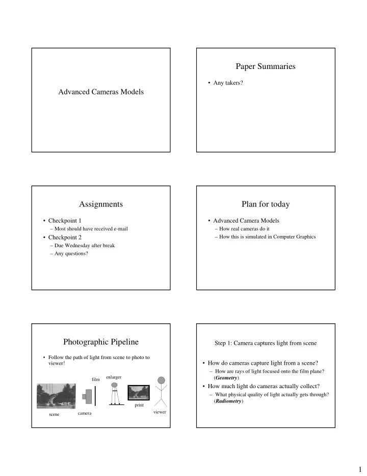
Photographic Pipeline
- Follow the path of light from scene to photo to
viewer!
scene camera film enlarger print viewer
Step 1: Camera captures light from scene
- How do cameras capture light from a scene?
– How are rays of light focused onto the film plane? (Geometry)
- How much light do cameras actually collect?