
SLIDE 1
page 2 of 81 Report reference No: 077-205588-000 Test - - PDF document
page 2 of 81 Report reference No: 077-205588-000 Test item description ................: Hot & Cold Water Purifier System Trade Mark ..................................: HYUNDAI WacorTec Co., Ltd. Manufacturer
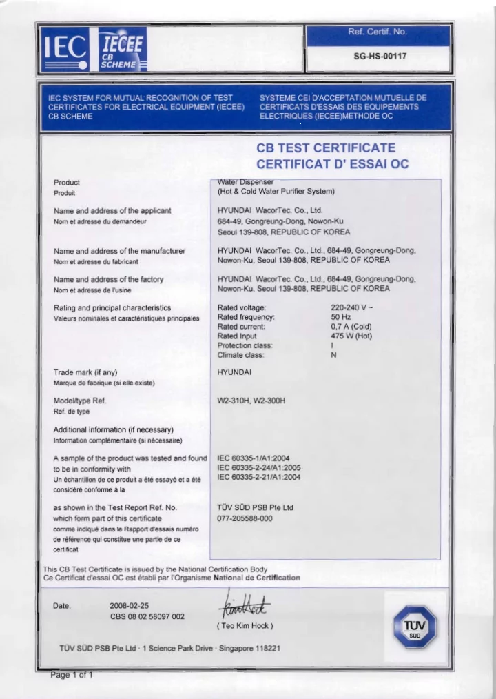
page 2 of 81 Report reference No: 077-205588-000 TRF No. IEC60335_2_24F Test item description ................: Hot & Cold Water Purifier System Trade Mark ..................................: Manufacturer ...............................: HYUNDAI WacorTec Co., Ltd. 684-49, Gongreung-dong, Nowon-Ku, Seoul, Korea Model /Type reference ................: W2-310H, W2-300H Ratings .........................................: 220 – 240 V ~; 50 Hz; 0.7 A (Cold); 475 W (Hot); Climate class N; IPX1 Copy of marking plate and summary of test results (information/comments): Summary of testing:
edition) + A1:2005 in conj. with IEC 60335-1:01 incl. Corr. 1:2002 + A1:2004 concerning cold water storage system in the product. Also was found to be in compliance with the test standards of IEC 60335-2-21:2002 (Fifth Edition) + A1:2004 concerning hot water storage system in the product.
page 3 of 81 Report reference No: 077-205588-000 TRF No. IEC60335_2_24F Test items particulars : Hot & Cold Water Purifier System Classification of installation and use............................: Stationary appliances / table-top or counter-top Supply Connection.......................................................: Supply cord with plug Possible test case verdicts : Test case does not apply to the test object................: N/A Test item does meet the requirement ........................: P(ass) Test item does not meet the requirement ..................: F(ail) Testing Date of receipt of test item .........................................: 2008-01-25 Date(s) of performance of test....................................: 2008-01-29 until 2008-02-12 Product verification per IECEE 02, Clause 6.2.5 . : Steps taken by the NCB to ensure that the products from all the factories stated in the CB Test Certificate are equal ...................................................: N/A General remarks This report is not valid as a CB Test Report unless signed by an approved CB Testing Laboratory and appended to a CB Test Certificate issued by an NCB in accordance with IECEE 02. The test results presented in this report relate only to the object tested. This report shall not be reproduced, except in full, without the written approval of the Issuing testing laboratory. "(see Enclosure #)" refers to additional information appended to the report. "(see appended table)" refers to a table appended to the report. Throughout this report a point is used as the decimal separator.
General product information:
heater.
Model no. W2-310H W2-300H Dimension (mm) 310 (W) x 310 (D) x 540 (H) 320 (W) x 320 (D) x 540 (H)
page 4 of 81 Report reference No: 077-205588-000 TRF No. IEC60335_2_24F IEC 60 335-2-24 Clause Requirement – Test Result – Remark Verdict 5 GENERAL CONDITIONS FOR THE TESTS Tests performed according to cl. 5, e.g. nature of supply, sequence of testing, etc. P 5.3 Before starting the tests (IEC 60335-2-24:2002):
rated voltage for 1 h N/A
P 5.4 Tests are additionally carried out with all combinations of energy sources supplied simultaneously unless this is prevented by interlocking devices (IEC 60335-2-24:2002) N/A 5.7 Tests according to sub-clause 10, 11,13 and subcl. 19.103 at ambient temperature of (IEC 60335-2-24:2002) : (23 + 2) °C for ice-cream appliances N/A (32 + 1) °C Climatic class SN N/A (32 + 1) °C Climatic class N P (38 + 1) °C Climatic class ST N/A (43 + 1) °C Climatic class T N/A 5.102 Compression-type appliances with heating systems and Peltier-type appliances are tested as combined appliances (IEC 60335-2-24:2002) P 6 CLASSIFICATION 6.1 Protection against electric shock: Class 0, 0I, I, II, III Class I P 6.2 Protection against harmful ingress of water IPX1 P 6.101 Appliances, other than ice-cream appliances, shall be of one or more of the following climatic classes: SN, N, ST, T (IEC 60335-2-24:2002) 7 MARKING AND INSTRUCTIONS 7.1 Rated voltage or voltage range (V): 220 – 240 V P Nature of supply: ~ P Rated frequency (Hz): 50 Hz P Rated power input (W): 475 W (hot water) P Rated current (A): 0.7 A (Cold water) P Manufacturer's or responsible vendor's name, trademark or identification mark: HYUNDAI WacorTec Co., Ltd. P Model or type reference: W2-310H, W2-300H P
page 5 of 81 Report reference No: 077-205588-000 TRF No. IEC60335_2_24F IEC 60 335-2-24 Clause Requirement – Test Result – Remark Verdict Symbol 5172 of IEC 60417, for Class II appliances N/A IP number, other than IPX0: IPX1 P Power input of heating systems, if greater than 100 W, (W) (IEC 60335-2-24:2002) 475 W (hot water) P Defrosting input, in W, if greater than the rated power input, (W) (IEC 60335-2-24:2002) N/A Rated power input in Watts (IEC 60335-2-24:2002) N/A Rated current in Amperes for compression-type appliances (IEC 60335-2-24:2002) 0.7A P Climatic class of the appliance (SN, N, ST or T) (IEC 60335-2-24:2002) N P Maximum rated input of lamps in Watts (IEC 60335-2-24:2002) N/A Total mass of the refrigerant (IEC 60335-2-24:2002) 35 g P For a single component refrigerant, at least one of the following (IEC 60335-2-24:2002) :
N/A
N/A
R-134a P For a blended refrigerant, at least one of the following (IEC 60335-2-24:2002) :
each of the components N/A
each of the components N/A
N/A
N/A The chemical name or refrigerant number of the insulation blowing gas (IEC 60335-2-24:2002) N/A Battery voltage for appliances which can be mains and battery operated (IEC 60335-2-24:2002) N/A
greater than 100 W (IEC 60335-2-24:2002) N/A Ice-makers shall be marked with the maximum permissible water level (IEC 60335-2-24:2002) N/A Compression-type refrigerating systems appliance shall be marked with mass of the refrigerant for each separate refrigerant circuit (IEC 60335-2-24:2002) N/A
page 6 of 81 Report reference No: 077-205588-000 TRF No. IEC60335_2_24F IEC 60 335-2-24 Clause Requirement – Test Result – Remark Verdict Compression-type appliances flammable which use refrigerants shall be marked with warning sign B.3.2 from ISO 3864 (IEC 60335-2-24:2002) N/A A The enclosure of electrically-operated water valves incorporated in external hose-sets for connection of an appliance to the water mains shall be marked with symbol IEC 60417-5036 (DB:2002-10) if their working voltage exceeds extra-low voltage (IEC 60335-1:01 + A1:2004) N/A 7.2 Warning for stationary appliances for multiple supply N/A Warning placed in vicinity of terminal cover N/A 7.3 Range of rated values marked with the lower and upper limits separated by a hyphen 220 – 240 V P Different rated values marked with the values separated by an oblique stroke N/A 7.4 Appliances adjustable for different rated voltages, the voltage setting is clearly discernible N/A 7.5 Appliances with more than one rated voltage or
rated input or rated current for each rated voltage
N/A the power input is related to the mean value of the rated voltage range P Relation between marking for upper and lower limits of rated power input or rated current and voltage is clear N/A 7.6 Correct symbols used P The perpendicular height of the triangle shall be at least 15 mm (IEC 60335-2-24:2002) N/A 7.7 Connection diagram fixed to appliances to be connected to more than two supply conductors and appliances for multiple supply N/A 7.8 Except for type Z attachment, terminals for connection to the supply mains indicated as follows:
conductor (N) N/A
(symbol 5019 of IEC 60417) P
P 7.9 Marking or placing of switches which may cause a hazard P 7.10 Indications of switches on stationary appliances and controls on all appliances by use of figures, letters or other visual means: P
page 7 of 81 Report reference No: 077-205588-000 TRF No. IEC60335_2_24F IEC 60 335-2-24 Clause Requirement – Test Result – Remark Verdict The figure 0 indicates only OFF position, unless no confusion with the OFF position Hot water switch: ON / OFF N/A See Note (IEC 60335-2-24:2002) N/A 7.11 Indication for direction of adjustment of controls N/A 7.12 Instructions for safe use provided P Instructions for refrigerating appliances and ice-makers for camping or similar use include the substance of the following (IEC 60335-2-24:2002) :
N/A
source of energy N/A
unless at least IPX4 N/A
the water supply WARNING: fill with potable water only N/A For compression-type appliances which use flammable refrigerants, instructions shall include information pertaining to the installation, handling, servicing (IEC 60335-2-24:2002) N/A The instructions shall include the warnings (IEC 60335-2-24:2002) N/A WARNING – Keep ventilation openings, in the appliance enclosure or in the built-in structure, clear of obstruction (IEC 60335-2-24:2002) N/A WARNING – Do not use mechanical devices or
manufacturer (IEC 60335-2-24:2002) N/A WARNING – Do not damage the refrigerant circuit (IEC 60335-2-24:2002) N/A WARNING – Do not use electrical appliances inside the food storage compartments of the appliance, unless they are of the type recommended by the manufacturer (IEC 60335-2-24:2002) N/A Appliances which use flammable insulation blowing gases, instructions shall include information regarding disposal of the appliance (IEC 60335-2-24:2002) N/A Instructions for ice-cream appliances shall include ingredients and max. quantity of mixtures that can be used in the appliance (IEC 60335-2-24:2002) N/A 7.12.1 Sufficient details for installation supplied P The method for replacing illuminating lamps included (IEC 60335-2-24:2002) N/A
page 8 of 81 Report reference No: 077-205588-000 TRF No. IEC60335_2_24F IEC 60 335-2-24 Clause Requirement – Test Result – Remark Verdict Appliances designed for incorporating ice- makers, the types of ice-makers (IEC 60335-2-24:2002) N/A Information on the installation of incorporated ice- makers as optional accessories (IEC 60335-2-24:2002) N/A Incorporated ice-makers installed only by the manufacturer or its service agent (IEC 60335-2-24:2002) N/A Ice makers intended to be connected to the water supply (IEC 60335-2-24:2002) :
(Pa) or (bar) N/A
necessary (Pa) or (bar) N/A WARNING: connect to potable water supply only (IEC 60335-2-24:2002) N/A Instructions for fixed appliances shall include the following warning (IEC 60335-2-24:2002) : WARNING: To avoid a hazard due to instability of the appliance, it must be fixed in accordance with the instructions (IEC 60335-2-24:2002) N/A 7.12.2 Stationary appliances not fitted with means for disconnection from the supply mains having a contact separation in all poles that provide full disconnection under overvoltage category III, the instructions state that means for disconnection must be incorporated in the fixed wiring in accordance with the wiring rules N/A 7.12.3 Insulation of the fixed wiring in contact with parts exceeding 50 K during clause 11; instructions stating that the fixed wiring must be protected N/A 7.12.4 Instructions for built-in appliances:
N/A
N/A
structure N/A
arrangement N/A
N/A
N/A a switch complying with 24.3 N/A Applicable to fixed appliances (IEC 60335-2-24:2002) N/A
page 9 of 81 Report reference No: 077-205588-000 TRF No. IEC60335_2_24F IEC 60 335-2-24 Clause Requirement – Test Result – Remark Verdict R - necessity to allow disconnection of the appliance from the supply after installation, unless the appliance incorporates a switch complying with 24.3 (IEC 60335-1:01 + A1:2004) N/A R - The disconnection may be achieved by having the plug accessible or by incorporating a switch in the fixed wiring in accordance with the wiring rules (IEC 60335-1:01 + A1:2004) N/A 7.12.5 Replacement cord instructions, type X attachment with a specially prepared cord N/A Replacement cord instructions, type Y attachment P Replacement cord instructions, type Z attachment N/A 7.12.6 A The instructions for heating appliances incorporating a non-self-resetting thermal cut-out that is reset by disconnection of the supply mains shall contain the substance of the following: (IEC 60335-1:01 + A1:2004) N/A A CAUTION: In order to avoid a hazard due to inadvertent resetting of the thermal cut-out, this appliance must not be supplied through an external switching device, such as a timer, or connected to a circuit that is regularly switched on and off by the utility. (IEC 60335-1:01 + A1:2004) N/A 7.12.7 The instructions for fixed appliances shall state how the appliance is to be fixed to its support (IEC 60335-1:01 + A1:2004) N/A 7.12.8 The instructions for appliances connected to the water mains shall state (IEC 60335-1:01 + A1:2004) P
P
this is necessary for the correct operation
P The instructions for appliances connected to the water mains by detachable hose-sets shall state that the new hose-sets supplied with the appliance are to be used and that old hose-sets should not be
P 7.13 Instructions and other texts in an official language P 7.14 Marking clearly legible and durable (IEC 60335-1:01 + A1:2004) P 7.15 Marking on a main part P Marking clearly discernible from the outside, if necessary after removal of a cover P For portable appliances, cover can be removed or
N/A
page 10 of 81 Report reference No: 077-205588-000 TRF No. IEC60335_2_24F IEC 60 335-2-24 Clause Requirement – Test Result – Remark Verdict For stationary appliances, name, trademark or identification mark and model or type reference visible after installation P For fixed appliances, name, trademark or identification mark and model or type reference visible after installation according to the instructions N/A Indications for switches and controls placed on or near the components. Marking not on parts which can be positioned or repositioned in such a way that the marking is misleading P
(IEC 60335-2-24:2002) N/A Compression-type appliances the marking of the type of flammable refrigerant and of the flammable insulation blowing gas, as well as the warning sign B.3.2 from ISO 3864, shall be visible when gaining access to the motor-compressors (IEC 60335-2-24:2002) N/A 7.16 Marking of a possible replaceable thermal link or fuse link clearly visible with regard to replacing the link P 7.101 Appliances which can be battery operated the connection shall be indicated by the symbol “+” or the colour red and “-“ or black (IEC 60335-2-24:2002) N/A 8 PROTECTION AGAINST ACCESS TO LIVE PARTS 8.1 Adequate protection against accidental contact with live parts P 8.1.1 Requirement applies for all positions, detachable parts removed P Insertion or removal of lamps, protection against contact with live parts of the lamp cap N/A Use of test probe B of IEC 61032: no contact with live parts P Removal of lamps: protection against contact with live parts (IEC 60335-2-24:2002) N/A 8.1.2 Use of test probe 13 of IEC 61032 through
appliances/ constructions: no contact with live parts P Test probe 13 also applied through openings in earthed metal enclosures having a non-conductive coating: no contact with live parts P 8.1.3 For appliances other than class II, use of test probe 41 of IEC 61032: no contact with live parts
N/A
page 11 of 81 Report reference No: 077-205588-000 TRF No. IEC60335_2_24F IEC 60 335-2-24 Clause Requirement – Test Result – Remark Verdict 8.1.4 Accessible part not considered live if:
exceeding 42.4 V N/A
42.4 V N/A
impedance N/A If protective impedance: d.c. current not exceeding 2 mA, and N/A a.c. peak value not exceeding 0.7 mA N/A
450 V, capacitance not exceeding 0,1 μF N/A
15 kV, discharge not exceeding 45 μC N/A The quantity of electricity in the discharge is measured using a resistor having a nominal non- inductive resistance of 2 000 Q. (IEC 60335-1:01 + A1:2004) N/A Number the existing note as Note 1 and add the following note: (IEC 60335-1:01 + A1:2004) N/A NOTE 2 The quantity of electricity is calculated from the sum of all areas recorded on the voltage/time graph without taking voltage polarity into account. (IEC 60335-1:01 + A1:2004) 8.1.5 Live parts protected at least by basic insulation before installation or assembly:
N/A
N/A
N/A 8.2 Class II appliances and constructions constructed so that there is adequate protection against accidental contact with basic insulation and metal parts separated from live parts by basic insulation
P Only possible to touch parts separated from live parts by double or reinforced insulation P 9 STARTING OF MOTOR-OPERATED APPLIANCES Not applicable 10 POWER INPUT AND CURRENT 10.1 Power input at normal operating temperature, rated voltage and normal operation not deviating from rated power input by more than shown in table 1 (see appended table) Hot water storage heater P
page 12 of 81 Report reference No: 077-205588-000 TRF No. IEC60335_2_24F IEC 60 335-2-24 Clause Requirement – Test Result – Remark Verdict Appliances being operated under normal
are set to give the lowest temperature (IEC 60335-2-24:2002) N/A The power input stabilized, steady conditions established (IEC 60335-2-24:2002) P A period between the making and the breaking of the temperature control, or highest and lowest values of power input measured (IEC 60335-2-24:2002) P 10.2 Current at normal operating temperature, rated voltage and normal operation not deviating from rated current by more than shown in table 2 (see appended table) Compressor for cold water P The appliance being operated under normal
are set to give the lowest temperature (IEC 60335-2-24:2002) P The appliance is operated for 1 h. The max. value
Starting after 1 min (IEC 60335-2-24:2002) P 10.101 The power input of the defrosting system, deviation shown in table 1 (IEC 60335-2-24:2002) N/A 10.102 The power input of any heating system, deviation shown in table 1 (IEC 60335-2-24:2002) P 11 HEATING 11.1 No excessive temperatures in normal use P If the winding temperatures of motor-compressors exceed the values given in table 101, compliance is checked by the test of 11.101 (IEC 60335-2-24:2002) N/A The winding temperatures of motor-compressors conforming IEC 60335-2-34 (incl. Annex AA) are not measured (IEC 60335-2-24:2002) N/A 11.2 Placing and mounting of appliance as described (IEC 60335-2-24:2002) P
N/A
N/A
P 11.3 Temperature rises, other than of windings, determined by thermocouples P Temperature rises of windings determined by resistance method, unless P the windings makes it difficult to make the necessary connections N/A
page 13 of 81 Report reference No: 077-205588-000 TRF No. IEC60335_2_24F IEC 60 335-2-24 Clause Requirement – Test Result – Remark Verdict 11.4 Heating appliances operated under normal
N/A 11.5 Motor-operated appliances operated under normal
0.94 and 1.06 times rated voltage: N/A 11.6 Combined appliances operated under normal
0.94 and 1.06 times rated voltage: P 11.7 The appliances is operated until steady conditions are established (IEC 60335-2-24:2002) P 11.8 Temperature rises not exceeding values in table 3 (see appended tables) P During the test protective devices do not operate (IEC 60335-2-24:2002) P During the test sealing compound doesn’t flow
P During the test temperatures are monitored conti- nuously (IEC 60335-2-24:2002) P For (SN) and (N) class, the temperature rises not exceeding values in table 3 (IEC 60335-2-24:2002) P For (ST) and (T) class, the temperature rises not exceeding values in table 3 reduced by 7 K (IEC 60335-2-24:2002) N/A The temperature rise of the external enclosure of motor-operated appliances not applicable for: (IEC 60335-2-24:2002)
N/A
P
P
compressors complying with (IEC 60 335-2-34) (IEC 60335-2-24:2002) N/A A However, components in protective electronic circuits are allowed to operate provided they are tested for the number of cycles of operation specified in 24.1.4. (IEC 60335-1:01 + A1:2004) N/A A The temperature of ballast windings and their associated wiring shall not exceed the values specified in 12.4 of IEC 60598-1, when measured under the conditions stated. (IEC 60335-2-24:2002/A1:2005) N/A 11.101 If the temperatures exceed the limits, the test is carried out again (IEC 60335-2-24:2002) :
cycle not higher than the limits given in table 101 N/A
page 14 of 81 Report reference No: 077-205588-000 TRF No. IEC60335_2_24F IEC 60 335-2-24 Clause Requirement – Test Result – Remark Verdict 11.102 Any defrosting system, temperature rises don’t exceed the values given in 11.8 (IEC 60335-2-24:2002) N/A Manual defrosting (IEC 60335-2-24:2002) N/A Automatic defrosting (IEC 60335-2-24:2002) N/A 11.103 Heating systems, other than defrosting, tempera- ture rises don’t exceed the values given in 11.8 (IEC 60335-2-24:2002) P 13 LEAKAGE CURRENT AND ELECTRIC STRENGTH AT OPERATING TEMPERATURE 13.1 Leakage current not excessive and electric strength adequate P Heating appliances operated at 1.15 times rated power input: N/A Motor-operated appliances and combined appliances supplied at 1.06 times rated voltage: P Protective impedance and radio interference filters disconnected before carrying out the tests N/A The test of 13.2 does not apply to battery circuit (IEC 60335-2-24:2002) N/A 13.2 Leakage current measured by means of the circuit described in figure 4 of IEC 60990 P Leakage current measurements and limits (IEC 60335-2-24:2002) (see appended table) P 13.3 Electric strength tests according to table 4 (see appended table) P No breakdown during the tests P The test voltage for reinforced insulation is applied between separate circuits for battery
(IEC 60335-2-24:2002) N/A The appliance is disconnected from the supply and the insulation is immediately subjected to a voltage having a frequency of 50 Hz or 60 Hz for 1 min, in accordance with IEC 61180-1.(IEC 60335-1:01 + A1:2004) P The high-voltage source used for the test is to be capable of supplying a short circuit current ls between the output terminals after the output voltage has been adjusted to the appropriate test
P The overload release of the circuit is not to be
lr The values of ls and lr are given in Table 5 for various high-voltage sources. (IEC 60335-1:01 + A1:2004) P
page 15 of 81 Report reference No: 077-205588-000 TRF No. IEC60335_2_24F IEC 60 335-2-24 Clause Requirement – Test Result – Remark Verdict 14 TRANSIENT OVERVOLTAGES Appliances withstand the transient overvoltages to which they may be subjected N/A Clearances having a value less than specified in table 16 subjected to an impulse voltage test, the test voltage specified in table 6 (see appended table) N/A No flashover during the test, unless of functional insulation N/A In case of flashover of functional insulation, the appliance complies with clause 19 with the clearance short circuited N/A 15 MOISTURE RESISTANCE 15.1 Enclosure provides the degree of moisture protection according to classification of the appliance IPX1 P Compliance checked as specified in 15.1.1, taking into account 15.1.2, followed by the electric strength test of 16.3 P No trace of water on insulation which can result in a reduction of clearances and creepage distances below values specified in clause 29 P 15.1.1 Appliances, other than IPX0, subjected to tests as specified in IEC 60529: P A Water valves containing live parts and that are incorporated in external hoses for connection of an appliance to the water mains are subjected to the test specified for IPX7 appliances. (IEC 60335-1:01 + A1:2004) N/A 15.1.2 Hand-held appliance turned continuously through the most unfavourable positions during the test N/A Built-in appliances installed according to the instructions N/A Appliances placed or used on the floor or table placed on a horizontal unperforated support P Appliances normally fixed to a wall and appliances with pins for insertion into socket-outlets are mounted on a wooden board N/A For IPX3 appliances, the base of wall mounted appliances is placed at the same level as the pivot axis of the oscillating tube N/A For IPX4 appliances, the horizontal centre line of the appliance is aligned with the pivot axis of the
N/A
page 16 of 81 Report reference No: 077-205588-000 TRF No. IEC60335_2_24F IEC 60 335-2-24 Clause Requirement – Test Result – Remark Verdict However, for appliances normally used on the floor
for a period of 5 min, the support being placed at the level of the pivot axis of the oscillating tube N/A Wall-mounted appliances, take into account the distance to the floor stated in the instructions N/A Appliances with type X attachment fitted with a flexible cord as described N/A Detachable parts tested as specified P Appliances normally fixed to a ceiling are mounted underneath a horizontal unperforated support that is constructed to prevent water spraying onto its top surface. The pivot axis of the oscillating tube is located at the same level as the underside of the support and aligned centrally with the appliance. The spray is directed
N/A For IPX4 appliances, the movement of the tube is limited to two times 90° from the vertical for a period of 5 min. (IEC 60335-1:01 + A1:2004) N/A 15.2 Spillage of liquid does not affect the electrical insulation P Appliances with type X attachment fitted with a flexible cord as described N/A Appliances incorporating an appliance inlet tested with or without an connector, whichever is most unfavourable N/A Detachable parts removed P Overfilling test with additional amount of water, over a period of 1 min (l): 0.6 (l) P The appliance withstands the electric strength test
P No trace of water on insulation that can result in a reduction of clearances and creepage distances below values specified in clause 29 P Lamp covers are not removed (IEC 60335-2-24:2002) N/A 15.3 Appliances proof against humid conditions 93 %RH, 30℃ P Humidity test for 48 h in a humidity cabinet P The appliance withstands the tests of clause 16 P 15.101 Spillage of liquid from inside does not affect their electrical insulation (IEC 60335-2-24:2002) N/A The relevant tests of 15.102, 15.103 and 15.104. are carried out (IEC 60335-2-24:2002) N/A
page 17 of 81 Report reference No: 077-205588-000 TRF No. IEC60335_2_24F IEC 60 335-2-24 Clause Requirement – Test Result – Remark Verdict 15.102 The apparatus shown in figure 101 is filled with water containing 1% NaCl and 0,6% of acid rinsing agent (IEC 60335-2-24:2002) N/A 15.103 Appliances, other than built-in appliances, ice-makers and ice-cream appliances, are tilted at an angle of up to 2° (IEC 60335-2-24:2002) N/A Test with 0,5 l water containing 1% NaCl and 0,6% of acid rinsing agent over the top of the appliance (IEC 60335-2-24:2002) N/A 15.104 Ice-makers which are directly connected to the water supply, is filled with water as in normal use. The inlet valve is then held open for 1 min (IEC 60335-2-24:2002) N/A 15.105 Operation of a defrosting system does not affect the electrical insulation of defrost heating elements (IEC 60335-2-24:2002) N/A If the water is in contact with the defrost heating element or its insulation, test of 22.102 is carried
N/A 16 LEAKAGE CURRENT AND ELECTRIC STRENGTH 16.1 Leakage current not excessive and electric strength adequate P Protective impedance disconnected from live parts before carrying out the tests N/A The test of 16.2 does not apply to battery circuits (IEC 60335-2-24:2002) N/A 16.2 Single-phase appliances: test voltage 1.06 times rated voltage: P Three-phase appliances: test voltage 1.06 times rated voltage divided by √3: N/A Leakage current measurements (see appended table) P Limits for class 0I appliances and the various types of class I appliances (IEC 60335-2-24:2002) (see appended table) P 16.3 Electric strength tests according to table 7 (see appended table) P No breakdown during the tests P The test voltage specified in Table 7 for reinforced insulation is applied between separate circuits for battery operation and mains supply
N/A
page 18 of 81 Report reference No: 077-205588-000 TRF No. IEC60335_2_24F IEC 60 335-2-24 Clause Requirement – Test Result – Remark Verdict 17 OVERLOAD PROTECTION OF TRANSFORMERS AND ASSOCIATED CIRCUITS No excessive temperatures in transformer or associated circuits in event of short-circuits likely to
(see appended table) N/A Appliance supplied with 1.06 or 0.94 times rated voltage and the most unfavourable short-circuit or
N/A Temperature rise of insulation of the conductors of safety extra-low voltage circuits not exceeding the relevant value specified in table 3 by more than 15 K N/A Temperature of the winding not exceeding the value specified in table 8, N/A however limits do not apply to fail-safe transformers complying with sub-clause 15.5 of IEC 61558-1 N/A 18 ENDURANCE Not applicable 19 ABNORMAL OPERATION 19.1 The risk of fire or mechanical damage under abnormal or careless operation obviated P Electronic circuits so designed and applied that a fault will not render the appliance unsafe P Subclauses 19.2 and 19.3 do not apply to heating systems (IEC 60335-2-24:2002) N/A Motor compressors not conforming to IEC 60335- 2-34 are subjected to the tests specified in IEC 60335-2-34 19.101, 19.102 and 19.104 (IEC60335-2-24:2002) N/A Fan motors of ice-cream appliances are not subject to the locked-rotor test specified in Annex (IEC 60335-2-24:2002) N/A 19.2 A Controls that operate during the test of Clause 11 are allowed to operate
(IEC 60335-1:01 + A1:2004)
19.3 A Controls that operate during the test of Clause 11 are allowed to operate
(IEC 60335-1:01 + A1:2004)
19.4 Test conditions as in cl. 11, any control limiting the temperature during tests of cl. 11 short-circuited P 19.5 Test of 19.4 repeated on Class 0I and I appliances with tubular sheathed or embedded heating
element connected to the elements sheath P
page 19 of 81 Report reference No: 077-205588-000 TRF No. IEC60335_2_24F IEC 60 335-2-24 Clause Requirement – Test Result – Remark Verdict The test repeated with reversed polarity and the
sheath P The test is not carried out on appliances intended to be permanently connected to fixed wiring and
N/A 19.6 Appliances with PTC heating elements tested at rated voltage, establishing steady conditions N/A The working voltage of the PTC heating element is increased by 5% and the appliance is operated until steady conditions are re-established. The voltage is then increased in similar steps until 1.5 times working voltage or until the PTC heating element ruptures N/A 19.7 Stalling test by locking the rotor if the locked rotor torque is smaller than the full load torque or locking moving parts of other appliances N/A Locked rotor, motor capacitors open-circuited or short-circuited, if required N/A Locked rotor, capacitors open-circuited one at a time N/A Test repeated with capacitors short-circuited one at a time, if required N/A Appliances with timer or programmer supplied with rated voltage for each of the tests, for a period equal to the maximum period allowed N/A Other appliances supplied with rated voltage for a period as specified N/A Winding temperatures not exceeding values specified in table 8 (see appended table) N/A Fan motors of ice-cream appliances are tested for 5 min (IEC 60335-2-24:2002) N/A 19.8 Three-phase motors operated at rated voltage with
N/A Three-phase motor compressors operated at rated voltage with one phase disconnected, unless complying with IEC 60335-2-34 (IEC 60335-2-24:2002) N/A 19.9 Not applicable 19.10 Series motor operated at 1.3 times rated voltage for 1 min: N/A During the test, parts not being ejected from the appliance N/A
page 20 of 81 Report reference No: 077-205588-000 TRF No. IEC60335_2_24F IEC 60 335-2-24 Clause Requirement – Test Result – Remark Verdict 19.11 Electronic circuits, compliance checked by evaluation of the fault conditions specified in 19.11.2 for all circuits or parts of circuits, unless they comply with the conditions specified in 19.11.1 P R Appliances incorporating a protective electronic circuit are subjected to the tests of 19.11.3 and 19.11.4. (IEC 60335-1:01 + A1:2004) N/A R Appliances having a switch with an off position
switch that can place the appliance in a stand-by mode, are subjected to the tests of 19.11.4. (IEC 60335-1:01 + A1:2004) N/A 19.11.1 Before applying the fault conditions a) to f) in 19.11.2, it is checked if circuits or parts of circuit meet both of the following conditions:
the maximum power at low-power points does not exceed 15 W according to the tests specified N/A
mechanical hazard or dangerous malfunction in
correct functioning of the electronic circuit N/A
mechanical hazard or dangerous malfunction in
correct functioning of the electronic circuit (IEC 60335-1:01 + A1:2004) N/A 19.11.2 Fault conditions applied one at a time, the appliance operated under conditions specified in cl. 11, but supplied at rated voltage, the duration of the tests as specified: a) short circuit of functional insulation if clearances
specified in 29 N/A b) open circuit at the terminals of any component P c) short circuit of capacitors, unless they comply with IEC 60384-14 N/A d) short circuit of any two terminals of an electronic component, other than integrated circuits. This fault condition is not applied between the two circuits of an optocoupler P e) failure of triacs in the diode mode N/A f) failure of an integrated circuit. The possible hazardous situations of the appliance are assessed to ensure that safety does not rely on the correct functioning of such a component N/A In this case the possible hazardous (IEC 60335-1:01 + A1:2004) N/A
page 21 of 81 Report reference No: 077-205588-000 TRF No. IEC60335_2_24F IEC 60 335-2-24 Clause Requirement – Test Result – Remark Verdict R In each case, the test is ended if a non-self- resetting interruption of the supply occurs within the appliance (IEC 60335-1:01 + A1:2004) N/A 19.11.3 If the appliance incorporates a protective electronic circuit which operates to ensure compliance with clause 19, the relevant test is repeated with a single fault simulated, as indicated in a) to f) of 19.11.2 N/A During and after each test the following is checked:
exceed the values specified in table 8 N/A
specified in 19.13 N/A
not exceeding the limits specified in 8.1.4 N/A If a conductor of a printed board becomes open-circuited, the appliance is considered to have withstood the particular test, provided all three of the following conditions are met:
withstands the burning test of annex E N/A
clearances or creepage distances between live parts and accessible metal parts below the values specified in cl. 29 N/A
N/A 19.11.4 A Appliances having a switch with an off position
that can be placed in the stand-by mode, are subjected to the tests of 19.11.4.1 to 19.11.4.7. The tests are carried out with the appliance supplied at rated voltage, the switch being set in the off position or in the stand-by mode. (IEC 60335-1:01 + A1:2004) N/A A Appliances incorporating a protective electronic circuit are subjected to the tests of 19.11.4.1 to 19.11.4.7. The tests are carried out after the protective electronic circuit has operated during the relevant tests of Clause 19 except 19.2, 19.6 and 19.11.3. However, appliances that are
are not subjected to the tests for electromagnetic
N/A A The tests are carried out with surge arresters disconnected, unless they incorporate spark
N/A
page 22 of 81 Report reference No: 077-205588-000 TRF No. IEC60335_2_24F IEC 60 335-2-24 Clause Requirement – Test Result – Remark Verdict A NOTE 1 If the appliance has several modes of operation, the tests are carried out with the
appliance operating in each mode, if necessary. (IEC 60335-1:01 + A1:2004)
A NOTE 2 Appliances incorporating electronic controls complying with the IEC 60730 series
are not exempt from the tests. (IEC 60335-1:01 + A1:2004)
19.11.4.1 The appliance is subjected to electrostatic discharges in accordance with IEC 61000-4-2, test level 4 being applicable. Ten discharges having a positive polarity and ten discharges having a negative polarity are applied at each preselected point. (IEC 60335-1:01 + A1:2004) N/A 19.11.4.2 The appliance is subjected to radiated fields in accordance with IEC 61000-4-3, test level 3 being applicable. (IEC 60335-1:01 + A1:2004) N/A 19.11.4.3 A The appliance is subjected to fast transient bursts in accordance with IEC 61000-4-4. (IEC 60335-1:01 + A1:2004) N/A A Test level 3 is applicable for signal and control
N/A A Test level 4 is applicable for the power supply
N/A A The bursts are applied for 2 min with a positive polarity and for 2 min with a negative polarity. (IEC 60335-1:01 + A1:2004) N/A A The power supply terminals of the appliance are subjected to voltage surges in accordance with IEC 61000-4-5, five positive impulses and five negative impulses being applied at the selected
N/A A Test level 3 is applicable for the line-to-line coupling mode, a generator having a source impedance of 2 Ω being used. (IEC 60335-1:01 + A1:2004) N/A A Test level 4 is applicable for the line-to-earth coupling mode, a generator having a source impedance of 12 Ω being used. (IEC 60335-1:01 + A1:2004) N/A A Earthed heating elements in class I appliances are disconnected during this test. (IEC 60335-1:01 + A1:2004) N/A A NOTE: If a feedback system depends on inputs related to a disconnected heating element, an artificial network may be needed. (IEC 60335-1:01 + A1:2004) A For appliances having surge arresters incorporating spark gaps, the test is repeated at a level that is 95 % of the flashover voltage. (IEC 60335-1:01 + A1:2004) N/A
page 23 of 81 Report reference No: 077-205588-000 TRF No. IEC60335_2_24F IEC 60 335-2-24 Clause Requirement – Test Result – Remark Verdict 19.11.4.5 A The appliance is subjected to injected currents in accordance with IEC 61000-4-6, test level 3 being
N/A A During the test, all frequencies between 0,15 MHz to 80 MHz are covered. (IEC 60335-1:01 + A1:2004) N/A A NOTE The dwell time for each frequency is to be sufficient to observe a possible
malfunction of the protective electronic circuit. (IEC 60335-1:01 + A1:2004)
19.11.4.6 A The appliance is subjected to voltage dips and interruptions in accordance with IEC 61000-4-11 (IEC 60335-1:01 + A1:2004) N/A A The durations specified in Table 1 of IEC 61000-4-11 are applied to each test level, the dips and interruptions being applied at zero crossing of the supply voltage. (IEC 60335-1:01 + A1:2004) N/A 19.11.4.7 A The appliance is subjected to mains signals in accordance with IEC 61000-4-13, test level class 2 being applicable (IEC 60335-1:01 + A1:2004) N/A 19.12 If the safety of the appliance for any of the fault conditions specified in 19.11.2 depends on the
IEC 60127, the test is repeated, measuring the current flowing through the fuse-link; measured current (A); rated current of the fuse-link (A): N/A 19.13 During the tests the appliance does not emit flames, molten metal, poisonous or ignitable gas in hazardous amounts P Temperature rises not exceeding the values shown in table 9 (see appended table) N/A Enclosures not deformed to such an extent that compliance with cl. 8 is impaired P If the appliance can still be operated it complies with 20.2 P Insulation, other than of class III appliance, withstand the electric strength test of 16.3, the test voltage specified in table 4:
1250V P
1750V P
3000V P Temperature rises not exceeding the values shown in table 7 or 150 °C for housing of motor- compressors (IEC 60335-2-24:2002) P A The appliance does not undergo a dangerous malfunction, and (IEC 60335-1:01 + A1:2004) N/A A no failure of protective electronic circuits, if the appliance is still operable (IEC 60335-1:01 + A1:2004) N/A
page 24 of 81 Report reference No: 077-205588-000 TRF No. IEC60335_2_24F IEC 60 335-2-24 Clause Requirement – Test Result – Remark Verdict A Appliances tested with an electronic switch in the
become operational (IEC 60335-1:01 + A1:2004) N/A 19.101 Heating systems dimensioned and located properly and comply with 19.13 during and after the test (IEC 60335-2-24:2002) P 19.102 Ice-makers and ice-cream appliances so constructed that they do not cause any risk and comply with 19.13 during and after the tests (IEC 60335-2-24:2002) N/A 19.103 Appliances intended for camping and similar use tested on an inclined support (5°) and comply with 19.13 during and after the test (IEC 60335-2-24:2002) N/A 19.104 Illuminating equipment shall not cause any fire hazard under abnormal operating conditions (IEC 60335-2-24:2002/A1:2005) N/A Test as specified (IEC 60335-2-24:2002/A1:2005) N/A Illuminating equipment having discharge lamps is
items a), d) and e) of 12.5.1 of IEC 60598-1, the appliance being supplied at rated voltage (IEC 60335-2-24:2002/A1:2005) N/A During the test, surrounding plastic parts shall not show any distortion which may affect safety in the sense of this standard (IEC 60335-2-24:2002/A1:2005) N/A The temperature of ballast windings shall not exceed the values specified in 12.5 of IEC 60598-1 when measured under the conditions specified (IEC 60335-2-24:2002/A1:2005) N/A 19.105 Appliances intended for battery operation properly constructed and comply with 19.13 during and after the test (IEC 60335-2-24:2002) N/A 20 STABILITY AND MECHANICAL HAZARDS 20.1 Adequate stability P Tilting test through an angle of 10° (appliance placed on an inclined plane/horizontal plane); appliance does not overturn P Tilting test repeated on appliances with heating elements, angle of inclination increased to 15° P Possible heating test in overturned position; temperature rise does not exceed values shown in table 9 N/A
page 25 of 81 Report reference No: 077-205588-000 TRF No. IEC60335_2_24F IEC 60 335-2-24 Clause Requirement – Test Result – Remark Verdict Ice-cream appliances shall have adequate stability (IEC 60335-2-24:2002) N/A 20.2 Moving parts adequately arranged or enclosed as to provide protection against personal injury N/A Protective enclosures, guards and similar parts are non-detachable N/A Adequate mechanical strength and fixing of protective enclosures N/A Self-resetting thermal cut-outs and overcurrent protective devices not causing a hazard, by unexpected reclosure N/A Not possible to touch dangerous moving parts with test probe N/A 20.101 Refrigeration appliances and ice-makers shall have adequate stability. Tests according to 20.102, 20.103 and 20.104 (IEC 60335-2-24:2002) N/A This requirement does not apply to built-in appliances (IEC 60335-2-24:2002) N/A 20.102 Test with door opened to 90° (IEC60335-2-24:2002 + A1:05) N/A Test with door opened to 180° or to the limit of door stop (IEC60335-2-24:2002 + A1:05) N/A 20.103 Test with one of the drawers is pulled to the most
N/A Test with two drawers are pulled to the most
N/A 20.104 Test with sliding drawers accessible without
N/A Doors shelves are loaded as specified in 20.102 and opened 90° (IEC 60335-2-24:2002) N/A 21 MECHANICAL STRENGTH Appliance has adequate mechanical strength and is constructed as to withstand rough handling P No damage after three blows applied to various parts of the enclosure, impact energy 0,5 ± 0,04 J P If necessary, supplementary or reinforced insulation subjected to the electric strength test of 16.3 N/A If necessary, repetition of groups of three blows on a new sample N/A Covers of lamps within the appliance are considered likely to be damaged in normal use. Lamps are not tested (IEC 60335-2-24:2002) N/A
page 26 of 81 Report reference No: 077-205588-000 TRF No. IEC60335_2_24F IEC 60 335-2-24 Clause Requirement – Test Result – Remark Verdict 21.1 R Compliance is checked by applying blows to the appliance in accordance with test Ehb of IEC 60068-2-75, the spring hammer test. (IEC 60335-1:01 + A1:2004) P R The appliance is rigidly supported and three blows, having an impact energy of 0,5 J, are applied to every point of the enclosure that is likely to be weak. (IEC 60335-1:01 + A1:2004) P 21.2 Accessible parts of solid insulation shall have sufficient strength to prevent Penetration by sharp
Results of cl.30.1 shows that no further tests are necessary
N/A A Compliance is checked by subjecting the insulation to the following test, unless the thickness of supplementary insulation is at least 1 mm and that of reinforced insulation is at least 2
Reinforced insulation is at least 2 mm N/A A The insulation is raised to the temperature measured during the test of Clause 11. Its tip is rounded with a radius of 0,25 mm ± 0,02 mm. (IEC 60335-1:01 + A1:2004) N/A A The surface of the insulation is then scratched by means of a hardened steel pin, the end of which has the form of a cone with an angle of 40°. (IEC 60335-1:01 + A1:2004) N/A A The pin is held at an angle of 80° - 85° to the horizontal and loaded so that the force exerted along its axis is 10 N ±0,5 N. (IEC 60335-1:01 + A1:2004) N/A A The scratches are made by drawing the pin along the surface of the insulation at a speed of approximately 20 mm/s. (IEC 60335-1:01 + A1:2004) N/A A Two parallel scratches are made. (IEC 60335-1:01 + A1:2004) N/A A They are spaced sufficiently apart so that they are not affected by each other, their length covering approximately 25 % of the length of the
N/A A Two similar scratches are made at 90° to the first pair without crossing them. (IEC 60335-1:01 + A1:2004) N/A A The test fingernail of Figure 7 is then applied to the scratched surface with a force of approximately 10 N. (IEC 60335-1:01 + A1:2004) N/A A No further damage, such as separation of the material, shall occur. (IEC 60335-1:01 + A1:2004) N/A A The insulation shall then withstand the electric strength test of 16.3. (IEC 60335-1:01 + A1:2004) N/A
page 27 of 81 Report reference No: 077-205588-000 TRF No. IEC60335_2_24F IEC 60 335-2-24 Clause Requirement – Test Result – Remark Verdict A The hardened steel pin is then applied perpendicularly with a force of 30 N ± 0,5 N to an unscratched part of the surface. (IEC 60335-1:01 + A1:2004) N/A A The insulation shall then withstand the electric strength test of 16.3 with the pin still applied and used as one of the electrodes (IEC 60335-1:01 + A1:2004) N/A 21.101 Appliances for camping or similar use tested against the effects of dropping and vibration as specified (IEC 60335-2-24:2002) N/A 21.102 Lamps are protected against mechanical shocks (IEC 60335-2-24:2002) N/A 22 CONSTRUCTION 22.1 Appliance marked with the first numeral of the IP system, relevant requirements of IEC 60529 are fulfilled IPX1 N/A 22.2 Stationary appliance: means to provide all-pole disconnection from the supply provided, the following means being available:
P
N/A
disconnection incorporated in the fixed wiring is to be provided N/A
N/A Singe-pole switches and single-pole protective devices for the disconnection of heating elements in single-phase permanently connected class I appliances, connected in the phase conductor N/A 22.3 Appliance provided with pins: no undue strain on socket-outlets N/A Applied torque not exceeding 0.25 Nm N/A Pull force of 50N to each pin after the appliance has being placed in the heating cabinet; when cooled to room temperature the pins are not displaced by more than 1mm N/A Each pin subjected to a tork of 0.4Nm; the pins are not rotating unless rotating does not impair compliance with the standard N/A 22.4 Appliance for heating liquids and appliance causing undue vibration not provided with pins for insertion into socket-outlets P 22.5 No risk of electric shock when touching the pins of the plug P
page 28 of 81 Report reference No: 077-205588-000 TRF No. IEC60335_2_24F IEC 60 335-2-24 Clause Requirement – Test Result – Remark Verdict R The appliance is supplied at rated voltage. Any switch is then placed in the off position and the appliance is disconnected from the supply mains at the instant of voltage peak. One second after disconnection, the voltage between the pins of the plug is measured with an instrument that does not appreciably affect the value to be measured (IEC 60335-1:01 + A1:2004) P 22.6 Electrical insulation not affected by condensing water or leaking liquid P Electrical insulation of Class II appliances not affected in case of a hose rupture or seal leak P Thermostats are not in contact with the evaporator unless they are adequately protected (IEC 60335-2-24:2002) P Fluids don’t flow along parts such as stems and tubes of thermostats (IEC 60335-2-24:2002) P 22.7 Compression-type appliances, including protective enclosures of a protected cooling system, using flammable refrigerants shall withstand (IEC 60335-2-24:2002)
pressure (70 °C) N/A
pressure (20 °C) N/A 22.8 Electrical connections not subject to pulling during cleaning of compartments to which access can be gained without the aid of a tool, and that are likely to be cleaned in normal use P 22.9 Insulation, internal wiring, windings, commutators and slip rings not exposed to oil, grease or similar substances P Adequate insulating properties of oil or grease to which insulation is exposed N/A 22.10 Location or protection of reset buttons of non-self- resetting controls is so that accidental resetting is unlikely P 22.10 R It shall not be possible to reset voltage- maintained non-self-resetting thermal cut-outs by the operation of an automatic switching device incorporated within the appliance. (IEC 60335-1:01 + A1:2004) N/A R Non-self-resetting thermal motor protectors shall have a trip-free action unless they are voltage
N/A
page 29 of 81 Report reference No: 077-205588-000 TRF No. IEC60335_2_24F IEC 60 335-2-24 Clause Requirement – Test Result – Remark Verdict
NOTE 2 Trip-free is an automatic action that is independent of manipulation or position of the actuating member. (IEC 60335-1:01 + A1:2004)
R Reset buttons of non-self-resetting controls shall be located or protected so that their accidental resetting is unlikely to occur if this could result in a hazard. (IEC 60335-1:01 + A1:2004) P
NOTE 3 For example, this requirement precludes the location of reset buttons on the back
22.11 Reliable fixing of non-detachable parts that provide the necessary degree of protection against electric shock, moisture or contact with moving parts P Obvious locked position of snap-in devices used for fixing such parts N/A No deterioration of the fixing properties of snap-in devices used in parts that are likely to be removed during installation or servicing N/A Tests as described P 22.12 Handles, knobs etc. fixed in a reliable manner P Fixing in wrong position of handles, knobs etc. indicating position of switches or similar components not possible N/A Axial force 15 N applied to parts, the shape being so that an axial pull is unlikely to be applied N/A Axial force 30 N applied to parts, the shape being so that an axial pull is likely to be applied P 22.13 Unlikely that handles, when gripped as in normal use, make the operators hand touch parts having a temperature rise exceeding the value specified for handles which are held for short periods only N/A 22.14 No ragged or sharp edges creating a hazard for the user in normal use, or during user maintenance P No exposed pointed ends of self tapping screws etc., liable to be touched by the user in normal use
P 22.15 Storage hooks and the like for flexible cords smooth and well rounded N/A 22.16 Automatic cord reels cause no undue abrasion or damage to the sheath of the flexible cord, no breakage of conductors strands, no undue wear of contacts N/A Cord reel tested with 6000 operations, as specified N/A Electric strength test of 16.3, voltage of 1000 V applied N/A 22.17 Spacers not removable from the outside by hand
N/A
page 30 of 81 Report reference No: 077-205588-000 TRF No. IEC60335_2_24F IEC 60 335-2-24 Clause Requirement – Test Result – Remark Verdict Not applicable to refrigeration appliances and ice-makers (IEC 60335-2-24:2002) 22.18 Current-carrying parts and other metal parts resistant to corrosion under normal conditions of use P 22.19 Driving belts not used as electrical insulation N/A 22.20 Direct contact between live parts and thermal insulation effectively prevented, unless material used is non-corrosive, non-hygroscopic and non- combustible N/A Compliance is checked by inspection and, if necessary, by appropriate test N/A 22.21 Wood, cotton, silk, ordinary paper and fibrous or hygroscopic material not used as insulation, unless impregnated P 22.22 Appliances not containing asbestos P 22.23 Oils containing polychlorinated biphenyl (PCB) not used P 22.24 Bare heating elements adequately supported N/A In case of rupture, the heating conductor is unlikely to come in contact with accessible metal parts N/A 22.25 Sagging heating conductors cannot come into contact with accessible metal parts N/A 22.26 The insulation between parts operating at safety extra-low voltage and other live parts complies with the requirements for double or reinforced insulation N/A 22.27 Parts connected by protective impedance separated by double or reinforced insulation N/A 22.28 Metal parts of Class II appliances conductively connected to gas pipes or in contact with water: separated from live parts by double or reinforced insulation N/A 22.29 Class II appliances permanently connected to fixed wiring so constructed that the required degree of access to live parts is maintained after installation N/A 22.30 Parts serving as supplementary or reinforced insulation fixed so that they cannot be removed without being seriously damaged, or P so constructed that they cannot be replaced in an incorrect position, and so that if they are omitted, the appliance is rendered inoperable or manifestly incomplete P 22.31 TME Clearances and creepage distances over supplementary and reinforced insulation not reduced below values specified in clause 29 as result of war P
page 31 of 81 Report reference No: 077-205588-000 TRF No. IEC60335_2_24F IEC 60 335-2-24 Clause Requirement – Test Result – Remark Verdict TME Clearances and creeping distances between live parts and accessible parts not reduced below values for supplementary insulation, if wires, screws, etc. become loose P 22.32 Supplementary and reinforced insulation designed
P Supplementary insulation of natural or synthetic rubber resistant to ageing, or arranged and dimensioned so that creepage distances are not reduced below values specified in 29.2 N/A Ceramic material not tightly sintered, similar material or beads alone not used as supplementary or reinforced insulation N/A Oxygen bomb test at 70 °C for 96 h and 16 h at room temperature N/A 22.33 Conductive liquids that are or may become accessible in normal use are not in direct contact with live parts P Electrodes not used for heating liquids not used P For class II constructions, conductive liquids that are or may become accessible in normal use, not in direct contact with basic or reinforced insulation P For class II constructions, conductive liquids which are in contact with live parts, not in direct contact with reinforced insulation N/A Heating conductors having only one layer of insulation are not in direct contact with water or ice during normal use (IEC 60335-2-24:2002) N/A NOTE : Frozen water is regarded as a conducting liquid (IEC 60335-2-24:2002) P 22.34 Shafts of operating knobs, handles, levers etc. not live, unless the shaft is not accessible when the part is removed P 22.35 Handles, levers and knobs, held or actuated in normal use, not becoming live in the event of an insulation fault P Such parts being of metal, and their shafts or fixings are likely to become live in the event of an insulation fault, they are either adequately covered by insulation material, or their accessible parts are separated from their shafts or fixings by supplementary insulation N/A This requirement does not apply to handles, levers and knobs on stationary appliances other than those of electrical components, provided they are either reliably connected to an earthing terminal or earthing contact, or separated from live parts by earthed metal N/A
page 32 of 81 Report reference No: 077-205588-000 TRF No. IEC60335_2_24F IEC 60 335-2-24 Clause Requirement – Test Result – Remark Verdict 22.36 Handles continuously held in the hand in normal use are so constructed that when gripped as in normal use, the operators hand is not likely to touch metal parts, unless they are separated from live parts by double or reinforced insulation N/A 22.37 Capacitors in Class II appliances not connected to accessible metal parts, unless complying with 22.42 N/A Metal casings of capacitors in Class II appliances separated from accessible metal parts by supplementary insulation, unless complying with 22.42 N/A 22.38 Capacitors not connected between the contacts of a thermal cut-out N/A 22.39 Lamp holders used only for the connection of lamps N/A 22.40 Motor-operated appliances and combined appliances intended to be moved while in
with a switch to control the motor. The actuating member of the switch being easily visible and accessible N/A 22.41 No components, other than lamps, containing mercury P 22.42 Protective impedance consisting of at least two separate components N/A Values specified in 8.1.4 not exceeded if any one
circuited N/A 22.43 Appliances adjustable for different voltages, accidental changing of the setting of the voltage unlikely to occur N/A 22.44 Appliances are not allowed to have an enclosure that is shaped and decorated so that the appliance is likely to be treated as a toy by children P 22.45 When air is used as reinforced insulation, clearances not reduced below the values specified in 29.1.4 due to deformation as a result of an external force applied to the enclosure P 22.46 A Software used in protective electronic circuits shall be software class B or software class C. (IEC 60335-1:01 + A1:2004) N/A A NOTE 1 Failure of software class B in the presence of another fault in the appliance, or
failure of software class C alone, could result in dangerous malfunction, electric shock, fire, mechanical or other hazards. Software class A denotes software used for functional
A Compliance is checked by evaluating the software in accordance with Annex R. (IEC 60335-1:01 + A1:2004) N/A
page 33 of 81 Report reference No: 077-205588-000 TRF No. IEC60335_2_24F IEC 60 335-2-24 Clause Requirement – Test Result – Remark Verdict A NOTE 2 If the software program is modified, the evaluation and relevant tests are repeated
if the modification can influence the results of the test involving protective electronic
22.47 A Appliances intended to be connected to the water mains shall withstand the water pressure expected in normal use. (IEC 60335-1:01 + A1:2004) P A No leakage from any part, including any inlet water hose (IEC 60335-1:01 + A1:2004) P A Compliance is checked by connecting the appliance to a water supply having a static pressure equal to twice the maximum inlet water pressure or 1,2 MPa, whichever is higher, for a period of 5 min. (IEC 60335-1:01 + A1:2004) P There shall be no leakage from any part, including any inlet water hose. (IEC 60335-1:01 + A1:2004) P 22.48 A Appliances intended to be connected to the water mains shall be constructed to prevent backsiphonage of non-potable water into the water mains. (IEC 60335-1:01 + A1:2004) N/A A Compliance is checked by the relevant tests of IEC 61770 (IEC 60335-1:01 + A1:2004) N/A 22.101 Lampholders properly fixed (IEC 60335-2-24:2002) N/A NOTE: Normal use includes replacement of lamps (IEC 60335-2-24:2002) N/A Test with torque of (IEC 60335-2-24:2002) : N/A 22.102 Insulated wire heaters and their joints protected against entry of water (IEC 60335-2-24:2002) N/A 3 heating elements: 24 h immersion in water with 1% NaCl; electric strength test between heating conductor and water (1250 V 15 min) (IEC 60335-2-24:2002) N/A 22.103 Ice-makers and appliances incorporating ice- makers withstand the water pressure as specified (IEC 60335-2-24:2002) N/A 22.104 Appliances with two or more temperature control devices controlling the same motor-compressor don’t cause undue operation of the thermal motor-protector (IEC 60335-2-24:2002) N/A The test is carried out separately with each combination of control devices (IEC 60335-2-24:2002) N/A 22.105 Appliances which can also be battery operated, the battery circuit is insulated from live parts by double insulation or reinforced insulation (IEC 60335-2-24:2002) N/A
page 34 of 81 Report reference No: 077-205588-000 TRF No. IEC60335_2_24F IEC 60 335-2-24 Clause Requirement – Test Result – Remark Verdict It is not possible to touch live parts when making the connections to the battery (IEC 60335-2-24:2002) N/A Specified for double insulation or reinforced insulation (IEC 60335-2-24:2002) N/A 22.106 The mass of refrigerant (flammable refrigerant) shall not exceed 150g (IEC 60335-2-24:2002) N/A 22.107 Compression-type appliances with a protected cooling system and which use flammable refrigerants shall be constructed to avoid any fire
the cooling system (IEC 60335-2-24:2002) use non-flammable refrigerants N/A 22.107.1 A leakage is simulated at the most critical point of the cooling system (method as specified) (IEC60335-2-24:2002 + A1:05) N/A The measured value shall not exceed 75% LEL of the refrigerant (table 102) and shall not exceed 50% LEL for a period exceeding 5 min. (IEC 60335-2-24:2002) N/A 22.107.2 All accessible surfaces of protected cooling system components, are scratched using the tool whose tip is shown in figure 102 (IEC 60335-2-24:2002) N/a The tool is applied using the following parameters (IEC 60335-2-24:2002) :
35 N + 3 N N/A
N/A The appropriate part shall withstand the test of 22.7 reduced by 50% (IEC 60335-2-24:2002) N/A 22.108 Compression-type appliances with unprotected cooling systems and which use flammable refrigerants, any electrical apparatus other than non-self resetting protective devices, shall be tested and found to comply with the requirements in Annex CC for group IIA gases or the refrigerant used (IEC60335-2-24:2002 + A1:05) N/A Refrigerant leakage into food storage shall not result in an explosive atmosphere outside the food storage compartment in areas where electrical apparatus are mounted, except in those areas which contain only non-self resetting protective devices, necessary for compliance with the requirements in Annex CC for group IIA gases or the refrigerant used (IEC60335-2-24:2002 + A1:05) N/A The measured value shall not exceed 75% LEL of the refrigerant (table 102) and shall not exceed 50% LEL for a period exceeding 5 min (IEC60335-2-24:2002 + A1:05) N/A
page 35 of 81 Report reference No: 077-205588-000 TRF No. IEC60335_2_24F IEC 60 335-2-24 Clause Requirement – Test Result – Remark Verdict 22.109 Compression-type appliance which use flammable refrigerants shall be constructed so that leaked refrigerant will not stagnate so as to cause a fire hazard in areas outside the food storage compartments where the appliance’s electrical components, other than non-self- resetting protective devices necessary for compliance with clause 19, are fitted (IEC60335-2-24:2002 + A1:05) N/A Unless the electrical components comply least with the requirements in Annex CC for group IIA gases or the refrigerant used (IEC60335-2-24:2002 + A1:05) N/A Test: A quantity equal to 50% + 1,5g of the refrigerant charge is injected into the considered area (IEC 60335-2-24:2002) N/A The measured value shall not exceed 75% LEL of the refrigerant (table 102) and shall not exceed 50% LEL for a period exceeding 5 min (IEC60335-2-24:2002 + A1:05) N/A 22.110 Temperatures on surfaces be exposed to leakage
ignition temperature (table 102) reduced by 100 K (IEC 60335-2-24:2002) N/A 22.111 Doors and lids of compartments in appliances with a free space shall be capable of being
N/A The door shall open before the force exceeds 70 N (IEC 60335-2-24:2002) N/A 22.112 Drawers which are only accessible after openings a door or lid shall not contain a free space (IEC 60335-2-24:2002) N/A 22.113 Drawers which are accessible with out opening a door and which contain a free space shall have an opening in their rear wall and be capable of being opened from the inside (IEC 60335-2-24:2002) N/A The drawers shall open before the force exceeds 70 N (IEC 60335-2-24:2002) N/A 22.114 Appliances for household use which contain compartments with a free space any door or drawer shall not be fitted with a self-latching lock (IEC 60335-2-24:2002) N/A Key operated locks shall require two independent movements to actuate the lock or be of a type that automatically ejects the key when unlocked (IEC 60335-2-24:2002) N/A
page 36 of 81 Report reference No: 077-205588-000 TRF No. IEC60335_2_24F IEC 60 335-2-24 Clause Requirement – Test Result – Remark Verdict 22.115 The fixing means for fixed appliances shall have adequate mechanical strength (IEC 60335-2-24:2002) N/A 23 INTERNAL WIRING 23.1 Wireways smooth and free from sharp edges P Wires protected against contact with burrs, cooling fins etc. P Wire holes in metal well rounded or provided with bushings P Wiring effectively prevented from coming into contact with moving parts N/A 23.2 Beads etc. on live wires cannot change their position, and are not resting on sharp edges or corners N/A Beads inside flexible metal conduits contained within an insulating sleeve N/A 23.3 Electrical connections and internal conductors movable relatively to each other not exposed to undue stress N/A Flexible metallic tubes not causing damage to insulation of conductors N/A Adequate insulating lining provided inside a coiled spring, the turns of which touch one another N/A No damage after 10 000 flexings for conductors flexed during normal use or 100 flexings for conductors flexed during user maintenance N/A Electric strength test, 1000 V between live parts and accessible metal parts N/A Open-coil springs not used. NOTE : It does not apply to external conductors (IEC 60335-2-24:2002) N/A 23.4 Bare internal wiring sufficiently rigid and fixed N/A 23.5 The insulation of internal wiring withstanding the electrical stress likely to occur in normal use P No breakdown when a voltage of 2000 V is applied for 15 min between the conductor and metal foil wrapped around the insulation P 23.6 Sleeving used as supplementary insulation on internal wiring retained in position by positive means N/A 23.7 The colour combination green/yellow used only for earthing conductors P 23.8 Aluminium wires not used for internal wiring P
page 37 of 81 Report reference No: 077-205588-000 TRF No. IEC60335_2_24F IEC 60 335-2-24 Clause Requirement – Test Result – Remark Verdict 23.9 No lead-tin soldering of stranded conductors where they are subject to contact pressure, unless P clamping means so constructed that there is no risk of bad contact due to cold flow of the solder N/A 23.10 A The insulation and sheath of internal wiring, incorporated in external hoses for the connection
least equivalent to that of light polyvinyl chloride sheathed flexible cord (code designation 60227 IEC 52) (IEC 60335-1:01 + A1:2004) N/A A NOTE The mechanical characteristics specified in IEC 60227 are not evaluated.
(IEC 60335-1:01 + A1:2004)
24 COMPONENTS 24.1 Components comply with safety requirements in relevant IEC standards P List of components (see appendix components) P Components not tested and found to comply with relevant IEC standard for the number of cycles specified are tested in accordance with 24.1.1 to 24.1.6 P Components not tested and found to comply with relevant IEC standard, components not marked or not used in accordance with its marking, tested under the conditions occurring in the appliance P Motor-compressors are not required to be separately tested according to (IEC 60 335-2-34) nor are they required to meet the requirements of (IEC 60 335-2-34) if they meet the requirements
P A Motors are not required to comply with IEC 60034-1.
(IEC 60335-1:01 + A1:2004)
N/A 24.1.1 Capacitors likely to be permanently subjected to the supply voltage and used for radio interference suppression or for voltage dividing, complying with IEC 60384-14, or N/A tested according to annex F N/A 24.1.2 Safety isolating transformers complying with IEC 61558-2-6, or N/A tested according to annex G N/A 24.1.3 Switches complying with IEC 61058-1, the number
P tested according to annex H N/A The number of operations for other switches (IEC 60335-2-24:2002) :
300 N/A
page 38 of 81 Report reference No: 077-205588-000 TRF No. IEC60335_2_24F IEC 60 335-2-24 Clause Requirement – Test Result – Remark Verdict
defrost switches 300 N/A
50’000 N/A
300 N/A A If the switch operates a relay or contactor, the complete switching system is subjected to the test (IEC 60335-1:01 + A1:2004) N/A A NOTE 2: Motor starting relays complying with IEC 60730-2-10 are not retested (IEC 60335-1:01 + A1:2004) 24.1.4 Automatic controls complying with IEC 60730-1 with relevant part 2. The number of cycles of operation being:
10 000 N/A
1 000 N/A
300 N/A
30 P R - voltage maintained non-self-resetting thermal cut-
1000 N/A R - other non-self-resetting thermal cut-outs: (IEC 60335-1:01 + A1:2004) 30 N/A
3 000 N/A
10 000 N/A
compressor: (IEC 60335-2-24:2002) 100'000 P
influence the test results of 19.101 and which are not short-circuited during this test: (IEC 60335-2-24:2002) 100'000 N/A
(IEC 60335-2-24:2002) 100'000 P
compressors of the hermetic and semi-hermetic type: minimum 2000, but not less than the number
(IEC 60335-2-24:2002) N/A
motor-compressors of the hermetic and semi- hermetic type: 50 (IEC 60335-2-24:2002) N/A
(IEC 60335-2-24:2002) 2000 N/A
(IEC 60335-2-24:2002) 30 N/A
page 39 of 81 Report reference No: 077-205588-000 TRF No. IEC60335_2_24F IEC 60 335-2-24 Clause Requirement – Test Result – Remark Verdict A NOTE 3 The ambient temperature during the test of Clause 17 of IEC 60730-1 is that
Table 3. (IEC 60335-1:01 + A1:2004)
R Thermal motor protectors are tested in combination with their motor under the conditions specified in Annex D (IEC 60335-1:01 + A1:2004) N/A R For water valves containing live parts and that are incorporated in external hoses for connection of an appliance to the water mains, the degree of protection declared for subclause 6.5.2 of IEC 60730-2-8 is IPX7 (IEC 60335-1:01 + A1:2004) N/A 24.1.5 Appliance couplers complying with IEC 60320-1 N/A However, appliances classified higher than IPX0, the appliance couplers complying with IEC 60320-2-3 N/A 24.1.6 Small lamp holders similar to E10 lampholders complying with IEC 60238, the requirements for E10 lampholders being applicable N/A 24.2 No switches or automatic controls in flexible cords P No devices causing the protective device in the fixed wiring to operate in the event of a fault in the appliance P No thermal cut-outs that can be reset by soldering P 24.3 Switches intended for all-pole disconnection of stationary appliances are directly connected to the supply terminals and having a contact separation in all poles, providing full disconnection under
N/A Appliances for camping or similar use (IEC 60335-2-24:2002) : Voltage selection switches used in appliances for camping or similar use shall have a contact separation in all poles that provide full disconnection from the supply under overvoltage category III conditions (IEC 60335-2-24:2002) N/A 24.4 Plugs and socket-outlets for extra-low voltage circuits and heating elements, not interchangeable with plugs and socket-outlets listed in IEC 60083
inlets complying with the standard sheets of IEC 60320-1 N/A 24.5 Capacitors in auxiliary windings of motors marked with their rated voltage and capacitance and used accordingly N/A Voltage across capacitors in series with a motor winding does not exceed 1,1 times rated voltage, when the appliance is supplied at 1,1 times rated voltage under minimum load N/A
page 40 of 81 Report reference No: 077-205588-000 TRF No. IEC60335_2_24F IEC 60 335-2-24 Clause Requirement – Test Result – Remark Verdict For starting capacitors, the voltage across the capacitors shall not exceed 1,3 times the rated voltage of the capacitor at 1.1xUn (IEC 60335-2-24:2002) N/A 24.6 Working voltage of motors connected to the supply mains and having basic insulation that is inadequate for the rated voltage of the appliance, not exceeding 42V. N/A In addition, the motors are complying with the requirements of Annex I N/A 24.7 A Hose-sets for connection of appliances to the water mains, complying with IEC 61770 and supplied with the appliance (IEC 60335-1:01 + A1:2004) P 24.101 Lampholders shall be of the insulated type (IEC 60335-2-24:2002) N/A 25 SUPPLY CONNECTION AND EXTERNAL FLEXIBLE CORDS Motor-compressors with facilities for connecting a supply cord, complying with the appropriate requirements of IEC 60 335-2-34 are not subjects to the following tests (IEC 60335-2-24:2002) N/A 25.1 Appliance not intended for permanent connection to fixed wiring, means for connection to the supply:
P
degree of protection against moisture as required for the appliance N/A
N/A 25.2 Appliance not provided with more than one means
P Stationary appliance for multiple supply may be provided with more than one means of connection, provided electric strength test of 1250 V for 1 min between each means of connection causes no breakdown N/A Mains-operated appliances provided with not more than one means of connection to the supply unless (IEC 60335-2-24:2002) P
completely independent units built together in one enclosure (IEC 60335-2-24:2002) N/A
from each other (IEC 60335-2-24:2002) N/A Appliances which can be both mains and battery
means for connection (IEC 60335-2-24:2002) N/A
page 41 of 81 Report reference No: 077-205588-000 TRF No. IEC60335_2_24F IEC 60 335-2-24 Clause Requirement – Test Result – Remark Verdict 25.3 Connection of supply conductors for appliance intended to be permanently connected to fixed wiring possible after the appliance has been fixed to its support N/A Appliance provided with a set of terminals for the connection of cables or fixed wiring, cross- sectional areas specified in 26.6 N/A Appliance provided with a set of terminals allowing the connection of a flexible cord N/A Appliance provided with a set of supply leads accommodated in a suitable compartment N/A Appliance provided with a set of terminals and cable entries, conduit entries, knock-outs or glands, allowing connection of appropriate type of cable or conduit N/A 25.4 Cable and conduit entries, rated current of appliance not exceeding 16 A, dimensions according to table 10 N/A Introduction of conduit or cable does not reduce clearances or creepage distances below values specified in 29 N/A 25.5 Method for assemble supply cord with the appliance:
N/A
P
N/A Type X attachment, other than those with a specially prepared cord, not used for flat twin tinsel cords N/A 25.6 Plugs fitted with only one flexible cord P 25.7 Supply cord not lighter than:
N/A
(60245 IEC 53) N/A
N/A
(60227 IEC 53), appliance exceeding 3 kg H05VV-F P Temperature rise of external metal parts exceeding 75 K, PVC cord not used, unless N/A appliance so constructed that the supply cord is not likely to touch external metal parts in normal use, or N/A the supply cord is appropriate for higher temperatures, type Y or type Z attachment used N/A
page 42 of 81 Report reference No: 077-205588-000 TRF No. IEC60335_2_24F IEC 60 335-2-24 Clause Requirement – Test Result – Remark Verdict Appliance supply cord other then SELV power supply not lighter than (IEC 60335-2-24:2002) :
designation 60227 IEC 52) N/A 25.8 Nominal cross-sectional area of supply cords according to table 11; rated current (A); cross- sectional area (mm²): 0.75 mm² P 25.9 Supply cord not in contact with sharp points or edges P 25.10 Green/yellow core for earthing purposes in Class I appliance P 25.11 Conductors of supply cords not consolidated by lead-tin soldering where they are subject to contact pressure, unless P clamping means so constructed that there is no risk of bad contacts due to cold flow of the solder N/A 25.12 Moulding the cord to part of the enclosure does not damage the insulation of the supply cord N/A 25.13 Inlet opening so shaped as to prevent damage to the supply cord P Unless the enclosure at the inlet opening is of insulation material, a non-detachable lining or bushing complying with 29.3 for supplementary insulation provided P If unsheathed supply cord, a similar additional bushing or lining is required, unless N/A the appliance is class 0 N/A Does not apply to flexible leads used to connected an appliance to a SELV power supply (IEC 60335-2-24:2002) N/A 25.14 Supply cords adequately protected against excessive flexing N/A Flexing test:
N/A
N/A The test does not result in:
N/A
conductor N/A
N/A
N/A
the cord or the cord guard N/A
page 43 of 81 Report reference No: 077-205588-000 TRF No. IEC60335_2_24F IEC 60 335-2-24 Clause Requirement – Test Result – Remark Verdict
becoming accessible N/A 25.15 Conductors of the supply cord relieved from strain, twisting and abrasion by use of cord anchorage P The cord cannot be pushed into the appliance to such an extent that the cord or internal parts of the appliance can be damaged P Pull and torque test of supply cord, values shown in table 10: pull (N); torque (not on automatic cord reel) (Nm) : 100 N; 0.35 Nm P
conductors not moved more than 1 mm in the terminals P Creepage distances and clearances not reduced below values specified in 29.1 P 25.16 Cord anchorages for type X attachments constructed and located so that:
N/A
prevention of twisting are obtained N/A
N/A
anchorage if these screws are accessible, unless separated from accessible metal parts by supplementary insulation N/A
bears directly on the cord N/A
fixed to the appliance, unless part of a specially prepared cord N/A
replacing the cord do not fix any other component, if applicable N/A
nevertheless withstood N/A
insulating material or are provided with an insulating lining, unless a failure of the insulation of the cord does not make accessible metal parts live N/A
material, or if of metal, they are insulated from accessible metal parts by supplementary insulation N/A 25.17 Adequate cord anchorages for type Y and Z attachment P 25.18 Cord anchorages only accessible with the aid of a tool, or P
page 44 of 81 Report reference No: 077-205588-000 TRF No. IEC60335_2_24F IEC 60 335-2-24 Clause Requirement – Test Result – Remark Verdict so constructed that the cord can only be fitted with the aid of a tool P 25.19 Type X attachment, glands not used as cord anchorage in portable appliances N/A Tying the cord into a knot or tying the cord with string not used N/A 25.20 Conductors of the supply cord for type Y and Z attachment adequately additionally insulated P 25.21 Space for supply cord for type X attachment or for connection of fixed wiring constructed to permit checking of conductors with respect to correct positioning and connection before fitting any cover, no risk of damage to the conductors when fitting the cover, no contact with accessible metal parts if a conductor becomes loose, etc. N/A For portable appliances, the uninsulated end of a conductor prevented from any contact with accessible metal parts, unless the end of the cord is such that the conductors are unlikely to slip free N/A 25.22 Appliance inlet:
removal N/A
N/A
N/A
metal parts exceeds 75 K, unless the supply cord is not likely to touch such metal parts N/A 25.23 Interconnection cords comply with the requirements for the supply cord, except as specified N/A If necessary, electric strength test of 16.3 N/A Interconnection cord for battery operated appliances (IEC 60335-2-24:2002) N/A 25.24 Interconnection cords not detachable without the aid of a tool if compliance with the standard is impaired when they are disconnected N/A 25.25 Dimensions of pins compatible with the dimensions of the relevant socket-outlet. Dimensions of pins and engagement face in accordance with the relevant plug in IEC 60083 N/A 25.101 Appliances which can be battery operated shall have suitable means for connection of the battery (IEC 60335-2-24:2002) N/A
page 45 of 81 Report reference No: 077-205588-000 TRF No. IEC60335_2_24F IEC 60 335-2-24 Clause Requirement – Test Result – Remark Verdict 26 TERMINALS FOR EXTERNAL CONDUCTORS This clause of part 1 is not applicable to those parts of motor-compressors with facilities for connecting a supply cord and complying with IEC 60 335-2-34 (IEC 60335-2-24:2002) N/A 26.1 Appliances provided with terminals or equally effective devices for connection of external conductors P Terminals only accessible after removal of a non- detachable cover P A However, earthing terminals may be accessible if a tool is required to make the connections and means are provided to clamp the wire independently from its connection (IEC 60335-1:01 + A1:2004) P 26.2 Appliances with type X attachment and appliances for connection to fixed wiring provided with terminals in which connections are made by means of screws, nuts or similar devices, unless the connections are soldered N/A Screws and nuts serve only to clamp supply conductors, except N/A internal conductors, if so arranged that they are unlikely to be displaced when fitting the supply conductors N/A If soldered connections used, the conductor so positioned or fixed that reliance is not placed on soldering alone N/A Soldering alone used, barriers provided, clearances and creepage distances satisfactory if the conductor becomes free at the soldered joint N/A 26.3 Terminals for type X attachment and for connection to fixed wiring so constructed that the conductor is clamped between metal surfaces with sufficient contact pressure and without damaging the conductor N/A Terminals for type X attachment and those for connection to fixed wiring so fixed that when tightening or loosening the clamping means:
N/A
N/A
reduced below the values in 29 N/A Compliance checked by inspection and by the test
applied being equal to two-thirds of the torque
category; torque (Nm): N/A
page 46 of 81 Report reference No: 077-205588-000 TRF No. IEC60335_2_24F IEC 60 335-2-24 Clause Requirement – Test Result – Remark Verdict 26.4 Terminals for type X attachment, except those with a specially prepared cord, and those for connection to fixed wiring, no special preparation
placed that conductors prevented from slipping out N/A 26.5 Terminals for type X attachment so located or shielded that if a wire of a stranded conductor escapes, no risk of accidental connection to other parts that result in a hazard N/A Stranded conductor test, 8 mm insulation removed N/A No contact between live parts and accessible metal parts and, for class II constructions, between live parts and metal parts separated from accessible metal parts by supplementary insulation
N/A 26.6 Terminals for type X attachment and for connection to fixed wiring suitable for connection of conductors with required cross-sectional area according to table 13; rated current (A); nominal cross-sectional area (mm²): N/A Terminals only suitable for a specially prepared cord N/A 26.7 Terminals for type X attachment accessible after removal of a cover or part of the enclosure N/A 26.8 Terminals for the connection to fixed wiring, including the earthing terminal, located close to each other N/A 26.9 Terminals of the pillar type constructed and located as specified N/A 26.10 Terminals with screw clamping and screwless terminals not used for flat twin tinsel cords, unless conductors ends fitted with a device suitable for screw terminals N/A Pull test of 5 N to the connection N/A 26.11 For type Y and Z attachment: soldered, welded, crimped and similar connections may be used P For Class II appliances: the conductor so positioned or fixed that reliance is not placed on soldering, welding or crimping alone N/A For Class II appliances: soldering, welding or crimping alone used, barriers provided, clearances and creepage distances satisfactory if the conductor becomes free N/A
page 47 of 81 Report reference No: 077-205588-000 TRF No. IEC60335_2_24F IEC 60 335-2-24 Clause Requirement – Test Result – Remark Verdict Terminals for type X attachment so located or shielded that if a wire of a stranded conductor escapes, no risk of accidental connection between live parts and accessible metal parts, between battery supply terminals if any (IEC 60335-2-24:2002) N/A 27 PROVISION FOR EARTHING Compliance is not checked on parts related to motor-compressors if the motor-compressor complies with IEC 60 335-2-34 (IEC 60335-2-24:2002) P 27.1 Accessible metal parts of Class 0I and I appliances, permanently and reliably connected to an earthing terminal or contact of the appliance inlet P Earthing terminals not connected to neutral terminal P Class 0, II and III appliance have no provision for earthing N/A Safety extra-low voltage circuits not earthed, unless protective extra-low voltage circuits N/A 27.2 Clamping means adequately secured against accidental loosening P Terminals used for the connection of external equipotential bonding conductors allow connection
N/A do not provide earthing continuity between different parts of the appliance N/A Conductors cannot be loosened without the aid of a tool N/A 27.3 For appliances with supply cord, current-carrying conductors become taut before earthing conductor, if the cord slips out of the cord anchorage P 27.3 A If a detachable part having an earth connection is plugged into another part of the appliance, the earth connection shall be made before the current-carrying connections are established. (IEC 60335-1:01 + A1:2004) N/A A The current-carrying connections shall be separated before the earth connection when removing the part (IEC 60335-1:01 + A1:2004) N/A 27.4 No risk of corrosion resulting from contact between metal of earthing terminal and other metal P Adequate resistance to corrosion of coated or uncoated parts providing earthing continuity, other than parts of a metal frame or enclosure P
page 48 of 81 Report reference No: 077-205588-000 TRF No. IEC60335_2_24F IEC 60 335-2-24 Clause Requirement – Test Result – Remark Verdict Parts of steel providing earthing continuity provided at the essential areas with an electroplated coating, thickness at least 5 µm P Adequate protection against rusting of parts of coated or uncoated steel, only intended to provide
P In case of aluminium alloys precautions taken to avoid risk of corrosion N/A 27.5 Low resistance of connection between earthing terminal and earthed metal parts P This requirement does not apply to connections providing earthing continuity in the protective extra- low voltage circuit, provided that clearances of basic insulation are based on the rated voltage of the appliance N/A Resistance not exceeding 0,1 Ω at the specified low-resistance test 0.053 Ω P 27.6 The printed conductors of printed circuit boards not used to provide earthing continuity in hand held appliances N/A They may be used in other appliances if:
soldering points and the appliance complies with requirements of 27.5 for each circuit N/A
with IEC 60249-2-4 or IEC 60249-2-5 N/A 28 SCREWS AND CONNECTIONS Compliance is not checked on parts related to motor-compressors if the motor-compressor complies with IEC 60 335-2-34 (IEC 60335-2-24:2002) P 28.1 Fixings, electrical connections and connections providing earthing continuity withstand mechanical stresses P Screws not of soft metal liable to creep, such as zinc or aluminium P Diameter of screws of insulating material min. 3 mm N/A Screws of insulating material not used for any electrical connection or connections providing earthing continuity P Screws used for electrical connections or connections providing earthing continuity screw into metal P
page 49 of 81 Report reference No: 077-205588-000 TRF No. IEC60335_2_24F IEC 60 335-2-24 Clause Requirement – Test Result – Remark Verdict Screws not of insulating material if their replacement by a metal screw can impair supplementary or reinforced insulation P Type X attachment, screws to be removed for replacement of supply cord or for user maintenance, not of insulating material if their replacement by a metal screw can impair basic insulation N/A For screws and nuts; test as specified (see appended table) P 28.2 Electrical connections and connections providing earthing continuity constructed so that contact pressure not transmitted through insulating material liable to shrink or distort, unless shrinkage
P This requirement does not apply to electrical connections in circuits carrying a current not exceeding 0.5A N/A 28.3 Space-threaded (sheet metal) screws only used for electrical connections if they clamp the parts together N/A Thread-cutting (self-tapping) screws only used for electrical connections if they generate a full form standard machine screw thread N/A Such screws not used if they are likely to be
is formed by a swaging action N/A Thread-cutting and space-threaded screws may be used in connections providing earthing continuity, provided unnecessary to disturb the connection and at least two screws are used for each connection P 28.4 Screws and nuts that make mechanical connection secured against loosening if they also make electrical connections or connections providing earthing continuity P Rivets for electrical connections or connections providing earthing continuity secured against loosening if subjected to torsion N/A 29 CLEARANCES, CREEPAGE DISTANCES AND SOLID INSULATION Compliance is not checked on parts related to motor-compressors if the motor-compressor complies with IEC 60 335-2-34 (IEC 60335-2-24:2002) P Clearances, creepage distances and solid insulation withstand electrical stress P
page 50 of 81 Report reference No: 077-205588-000 TRF No. IEC60335_2_24F IEC 60 335-2-24 Clause Requirement – Test Result – Remark Verdict For coatings used on printed circuits boards to protect the microenvironment or to provide basic insulation, annex J applies N/A R If coatings are used on printed circuit boards to protect the microenvironment (Type A coating) or to provide basic insulation (Type B coating), Annex J applies. (IEC 60335-1:01 + A1:2004) N/A R The microenvironment is pollution degree 1 under Type A coating. (IEC 60335-1:01 + A1:2004) N/A R There are no creepage distance or clearance requirements under Type B coating. (IEC 60335-1:01 + A1:2004) N/A 29.1 Clearances not less than the values specified in table 16, taking into account the rated impulse voltage for the overvoltage categories of table 15 (see appended table) P The values specified may be smaller for basic insulation and functional insulation if the clearance meets the impulse voltage test of clause 14 N/A Appliances are in overvoltage category II P Clearances less than specified in table 16 not allowed for basic insulation of class 0 and class 0I appliances, N/A
N/A Compliance is checked by inspection and measurements as specified P 29.1 R Clearances not less than the values specified in table 16, taking into account the rated impulse voltage for the overvoltage categories of table 15, unless for basic insulation and functional insulation they comply with the impulse voltage test of clause 14 (IEC 60335-1:01 + A1:2004) P R However, if the construction is affected by wear, distortion, movement of the parts or during assembly, the clearances for rated impulse voltages of 1500V and above are increased by 0,5 mm and the impulse voltage test is not applicable (IEC 60335-1:01 + A1:2004) N/A R The impulse voltage test is not applicable when the microenvironment is pollution degree 3 or for basic insulation of class 0 appliances and class 0I appliances (IEC 60335-1:01 + A1:2004) N/A R Lacquered conductors of windings considered to be bare conductors (IEC 60335-1:01 + A1:2004) N/A 29.1.3 Clearances of reinforced insulation not less than those specified for basic insulation in table 16, but using the next higher step for rated impulse voltage P
page 51 of 81 Report reference No: 077-205588-000 TRF No. IEC60335_2_24F IEC 60 335-2-24 Clause Requirement – Test Result – Remark Verdict 29.1.4 For functional insulation, the values of table 16 are applicable, unless P the appliance complies with clause 19 with the functional insulation short-circuited N/A Clearances at crossover points of lacquered conductors not measured N/A Clearance between surfaces of PTC heating elements may be reduced to 1mm N/A Lacquered conductors of windings assumed to be bare conductors, but the clearances specified in table 16 are reduced by 0.5mm for rated impulse voltages of at least 1500V N/A R Lacquered conductors of windings considered to be bare conductors (IEC 60335-1:01 + A1:2004) N/A R However, clearances at crossover points are not measured (IEC 60335-1:01 + A1:2004) N/A 29.1.5 Appliances having higher working voltage than rated voltage, the voltage used for determining clearances from table 16 is the sum of the rated impulse voltage and the difference between the peak value of the working voltage and the peak value of the rated voltage N/A If the secondary winding of a step-down transformer is earthed, or if there is an earthed screen between the primary and secondary windings, clearances of basic insulation on the secondary side not less than those specified in table 16, but using the next lower step for rated impulse voltage N/A Circuits supplied with a voltage lower than rated voltage, clearances of functional insulation based
table 15 N/A 29.2 Creepage distances not less than those appropriate for the working voltage, taking into account the material group and the pollution degree P Pollution degree 2 applies, unless P precautions taken to protect the insulation; pollution degree 1 N/A insulation subjected to conductive pollution; pollution degree 3 P Compliance is checked by inspection and measurements as specified P
page 52 of 81 Report reference No: 077-205588-000 TRF No. IEC60335_2_24F IEC 60 335-2-24 Clause Requirement – Test Result – Remark Verdict Insulation in refrigeration appliances and ice- makers is in pollution degree 3 and shall have a CTI value of 250 unless the insulation to be protected to pollution by condensation (IEC 60335-2-24:2002) P 29.2.1 Creepage distances of basic insulation not less than specified in table 17 (see appended table) P For pollution degree 1, creepage distance not less than the minimum specified for the clearance in table 16, if the clearance has been checked according to the test of clause 14 N/A 29.2.2 Creepage distances of supplementary insulation at least as specified for basic insulation in table 17 P 29.2.3 Creepage distances of reinforced insulation at least double as specified for basic insulation in table 17 P 29.2.4 Creepage distances of functional insulation not less than specified in table 18 P Creepage distances may be reduced if the appliance complies with clause 19 with the functional insulation short-circuited N/A 29.3 R Supplementary insulation and reinforced insulation shall have adequate thickness, or have a sufficient number of layers, to withstand the electrical stresses that can be expected during the use of the appliance. (IEC 60335-1:01 + A1:2004) P R Compliance checked by: (IEC 60335-1:01 + A1:2004)
P R - an electric strength test in accordance with 29.3.2, if the insulation consists of more than one separate layer, other than natural mica or similar flaky material, or by (IEC 60335-1:01 + A1:2004) N/A R - an assessment of the thermal quality of the material combined with an electric strength test, in accordance with 29.3.3 (IEC 60335-1:01 + A1:2004) N/A 29.3.1 R The thickness of the insulation shall be at least (IEC 60335-1:01 + A1:2004)
P 29.3.2 R Each layer of material shall withstand the electric strength test of 16.3 for supplementary insulation. (IEC 60335-1:01 + A1:2004) N/A R Supplementary insulation shall consist of at least 2 layers of material and reinforced insulation of at least 3 layers (IEC 60335-1:01 + A1:2004) N/A
page 53 of 81 Report reference No: 077-205588-000 TRF No. IEC60335_2_24F IEC 60 335-2-24 Clause Requirement – Test Result – Remark Verdict 29.3.3 R The insulation is subjected to the dry heat test Bb
temperature of 50 K in excess of the maximum temperature rise measured during the test of Clause 19. (IEC 60335-1:01 + A1:2004) N/A R At the end of the period, the insulation is subjected to the electric strength test of 16.3 at the conditioning temperature and also after it has cooled down to room temperature (IEC 60335-1:01 + A1:2004) N/A R If the temperature rise of the insulation measured during the tests of Clause 19 does not exceed the value specified in Table 3, the test of IEC 60068-2-2 is not carried out. (IEC 60335-1:01 + A1:2004) N/A 30 RESISTANCE TO HEAT AND FIRE 30.1 External parts of non-metallic material, P parts supporting live parts, and P thermoplastic material providing supplementary or reinforced insulation, P sufficiently resistant to heat P Ball-pressure test according to IEC 60695-10-2 (see appended table) P External parts: at 40 °C plus the maximum temperature rise determined during the test of clause 11, or at 75 °C, whichever is the higher; temperature (°C): P Parts supporting live parts: at 40°C plus the maximum temperature rise determined during the test of clause 11, or at 125°C, whichever is the higher; temperature (°C): P Parts of thermoplastic material providing supplementary or reinforced insulation, 25°C plus the maximum temperature rise determined during clause 19, if higher; temperature (°C): N/A Relevant external parts of non-metallic material also within the storage compartment parts (IEC 60335-2-24:2002) N/A Accessible parts within the storage compartment 65 °C (IEC 60335-2-24:2002) N/A Following tests do not apply to parts related to the motor-compressor if the motor-compressor complies with IEC 60 335-2-34 (IEC 60335-2-24:2002) P 30.2 Relevant parts of non-metallic material adequately resistant to ignition and spread of fire (see appended table) P
page 54 of 81 Report reference No: 077-205588-000 TRF No. IEC60335_2_24F IEC 60 335-2-24 Clause Requirement – Test Result – Remark Verdict Following tests do not apply to parts related to the motor-compressor if the motor-compressor complies with IEC 60 335-2-34 with no ignition (IEC 60335-2-24:2002) P 30.2.1 Glow-wire test of IEC 60695-2-11 at 550 °C, unless P the material is classified at least HB40 according to IEC 60695-11-10 N/A Parts for which the glow-wire test cannot be carried out meet the requirements in ISO9772 for category FH3 material N/A Parts for which the glow-wire test cannot be carried out meet the requirements in ISO9772 for category HBF material (IEC 60335-1:01 + A1:2004) N/A 30.2.2 Not applicable 30.2.3 Appliances operated while unattended, tested as specified in 30.2.3.1 and 30.2.3.2 P Test not applicable to conditions as specified N/A 30.2.3.1 Parts of insulating material supporting connections carrying a current exceeding 0.2A during normal
P parts of insulating material within a distance of 3mm, P having a glow-wire flammability index of at least 850°C according to IEC 60695-2-12 P 30.2.3.2 Parts of insulating material supporting current- carrying connections, and P parts of insulating material within a distance of 3mm, P subjected to glow-wire test of IEC 60695-2-11 P Test not carried out on material having a glow-wire ignition temperature according to IEC 60695-2-13 as specified N/A Glow-wire test of IEC 60695-2-11, the temperature being:
exceeding 0,2A during normal operation P
N/A Parts that during the test produce a flame persisting longer than 2 s, tested as specified N/A If a flame persists longer than 2 s during the test, parts above the connection, as specified, subjected to the needle-flame test of annex E, unless N/A
page 55 of 81 Report reference No: 077-205588-000 TRF No. IEC60335_2_24F IEC 60 335-2-24 Clause Requirement – Test Result – Remark Verdict the material is classified as V-0 or V-1 according to IEC 60695-11-10 N/A 30.2.4 Base material of printed circuit boards subjected to needle-flame test of annex E P Test not applicable to conditions as specified N/A 31 RESISTANCE TO RUSTING Relevant ferrous parts adequately protected against rusting P 32 RADIATION, TOXICITY AND SIMILAR HAZARDS Not applicable A ANNEX A (INFORMATIVE) ROUTINE TESTS Description of routine tests to be carried out by the manufacturer P AA ANNEX AA, (NORMATIVE) LOCKED-ROTOR TEST OF FAN MOTORS (IEC 60335-2-24:2002) The winding of a fan motor does not reach excessive temperatures if the motor locks or fails to start (see appended table) N/A The motor is supplied at rated voltage according to supply circuit fig. AA.1. N/A B ANNEX B (NORMATIVE) APPLIANCES POWERED BY RECHARGEABLE BATTERIES The following modifications to this standard are applicable for appliances powered by batteries that are recharged in the appliance N/A This annex does not apply to battery chargers N/A 3.1.9 Appliance operated under the following conditions:
battery, operated as specified in relevant part 2 N/A
discharged to such an extent that the appliance cannot operate N/A
supply mains through its battery charger, the battery being initially discharged to such an extent that the appliance cannot operate. The appliance is operated as specified in relevant part 2 N/A
page 56 of 81 Report reference No: 077-205588-000 TRF No. IEC60335_2_24F IEC 60 335-2-24 Clause Requirement – Test Result – Remark Verdict If the appliance incorporates inductive coupling between two parts that are detachable from each
mains with the detachable part removed N/A 3.6.2 Part to be removed in order to discard the battery is not considered to be detachable N/A 5.101 Appliances supplied from the supply mains tested as specified for motor-operated appliances N/A 7.1 Battery compartment for batteries intended to be replaced by the user, marked with battery voltage and polarity of the terminals N/A 7.12 The instructions for appliances incorporating batteries intended to be replaced by the user includes required information N/A Details about how to remove batteries containing materials hazardous to the environment given N/A 7.15 Markings placed on the part of the appliance connected to the supply mains N/A 8.2 Appliances having batteries that according to the instruction may be replaced by the user need only have basic insulation between live parts and the inner surface of the battery compartment N/A If the appliance can be operated without batteries, double or reinforced insulation required N/A 11.7 The battery is charged for the period described N/A 19.1 Appliances subjected to tests of 19.101, 19.102 and 19.103 N/A 19.101 Appliances supplied at rated voltage for 168 h, the battery being continually charged N/A 19.102 Short-circuiting of the terminals of the battery, being fully charged, for appliances having batteries that can be removed without the aid of a tool N/A 19.103 Appliances having batteries replaceable by the user supplied at rated voltage under normal
position allowed by the construction N/A 21.101 Appliances having pins for insertion into socket-
checked according to procedure 2 of IEC 68-2-32 N/A Part of the appliance incorporating the pins subjected to the free fall test, procedure 2, of IEC 60068-2-32, the number of falls being:
N/A
N/A After the test, the requirements of 8.1, 15.1.1, 16.3 and clause 29 are met N/A
page 57 of 81 Report reference No: 077-205588-000 TRF No. IEC60335_2_24F IEC 60 335-2-24 Clause Requirement – Test Result – Remark Verdict 22.3 Appliances having pins for insertion into socket-
N/A 25.13 An additional lining or bushing not required for interconnection cords operating at safety extra-low voltage N/A 30.2 For parts of the appliance connected to the supply mains during the charging period, 30.2.3 applies N/A For other parts, 30.2.2 applies N/A C ANNEX C (NORMATIVE) AGEING TEST ON MOTORS Tests, as described, carried out when doubt with regard to the temperature classification of the insulation of a motor winding N/A This annex does not apply to motor-compressors (IEC 60335-2-24:2002) N/A CC ANNEX CC (NORMATIVE) NON-SPARKING “N” ELECTRICAL APPARATUS Where reference is made to IEC 60079-15, the following clauses are applicable as modified below (IEC 60335-2-24:2002/A1:2005) 21 Supplementary requirements for non-sparking luminaires (IEC 60335-2-24:2002/A1:2005) All of subclauses of Clause 21 are applicable, except 21.2.5.1, 21.2.5.5, 21.2.7, 21.2.8, 21.2.9, 21.2.10, 21.2.11, 21.2.12 and 21.3 (IEC 60335-2-24:2002/A1:2005) N/A 29 Supplementary requirements for sealed devices or encapsulated devices producing arcs, sparks or hot surfaces (IEC 60335-2-24:2002/A1:2005) All of the subclauses of Clause 29 are applicable, except 29.1 and 29.8, which are replaced by the following (IEC 60335-2-24:2002/A1:2005) N/A 29.1 Non metallic materials (IEC 60335-2-24:2002/A1:2005) Seals are tested using 33.5. However if the device is tested in the appliance, then 33.5.1 and 33.5.1 are not applicable. (IEC 60335-2-24:2002/A1:2005) N/A However, after the tests of Clause 19 in IEC 60335-2-24, by inspection, no damage of the encapsulation that could impair the type of protection shall be evident, such as cracks in the resin or exposure of encapsulated parts (IEC 60335-2-24:2002/A1:2005) N/A 29.8 Type tests (IEC 60335-2-24:2002/A1:2005)
page 58 of 81 Report reference No: 077-205588-000 TRF No. IEC60335_2_24F IEC 60 335-2-24 Clause Requirement – Test Result – Remark Verdict The type tests described in 33.5 shall be performed where relevant (IEC 60335-2-24:2002/A1:2005) N/A 30 Supplementary requirements for energy-limited apparatus and circuits producing arcs, sparks or hot surfaces (IEC 60335-2-24:2002/A1:2005) All of the subclauses of Clause 30 are applicable, except 30.5, 30.6 and 30.10 N/A 31 Supplementary requirements for restricted-breathing enclosures protecting apparatus producing arcs, sparks or hot surfaces (IEC 60335-2-24:2002/A1:2005) All of the subclauses of Clause 31 are applicable, except 31.6 which is replaced by the following N/A 31.6 Restricted-breathing enclosures shall be type tested, including the cable entry devices (IEC 60335-2-24:2002/A1:2005) N/A D ANNEX D (NORMATIVE) ALTERNATIVE REQUIREMENTS FOR PROTECTED MOTORS Applicable to protected motors for unattended use, test of 19.7 carried out on a separate sample according to the specification N/A This annex does not apply to motor-compressors
N/A This annex is applicable to appliances having motors that incorporate thermal motor protectors (IEC 60335-1:01 + A1:2004). N/A The appliance is supplied at rated voltage with the rotor of the motor locked. (IEC 60335-1:01 + A1:2004) N/A The duration of the test is as follows: (IEC 60335-1:01 + A1:2004)
protectors are operated for 300 cycles or for 72 h, whichever occurs first, unless they are likely to be permanently subjected to the supply voltage in which case the duration is 432 h; (IEC 60335-1:01 + A1:2004) N/A
protectors are operated for 30 cycles, the thermal motor protector being reset as soon as possible after each operation, but in not less than 30 s; (IEC 60335-1:01 + A1:2004) N/A During the test, temperatures shall not exceed the values specified in 19.7 and the appliance shall comply with 19.13 (IEC 60335-1:01 + A1:2004) N/A
page 59 of 81 Report reference No: 077-205588-000 TRF No. IEC60335_2_24F IEC 60 335-2-24 Clause Requirement – Test Result – Remark Verdict
NOTE This test may be carried out on a separate appliance.
(IEC 60335-1:01 + A1:2004) E ANNEX E (NORMATIVE) NEEDLE-FLAME TEST Needle-flame test carried out in accordance with IEC 60695-2-2, with the following modifications: P 5 Severities The duration of application of the test flame is 30 s ± 1 s N/A 8 Test procedure 8.2 The specimen so arranged that the flame can be applied to a vertical or horizontal edge as shown in the examples of figure 1 P 8.4 The first paragraph does not apply P If possible, the flame is applied at least 10 mm from a corner P 8.5 The test is carried out on one specimen P If the specimen does not withstand the test, the test may be repeated on two further specimens, both withstanding the test N/A 10 Evaluation of test results The duration of burning not exceeding 30 s N/A However, for printed circuit boards, the duration of burning not exceeding 15 s P F ANNEX F (NORMATIVE) CAPACITORS Capacitors likely to be permanently subjected to the supply voltage, and used for radio interference suppression or voltage dividing, comply with the following clauses of IEC 60384-14, with the following modifications:
Terminology 1.5.3 Class X capacitors tested according to subclass X2 N/A 1.5.4 This subclause is applicable N/A 1.6 Marking Items a) and b) are applicable N/A 3.4 Approval testing 3.4.3.2 Table II is applicable as described N/A
page 60 of 81 Report reference No: 077-205588-000 TRF No. IEC60335_2_24F IEC 60 335-2-24 Clause Requirement – Test Result – Remark Verdict 4.1 Visual examination and check of dimensions This subclause is applicable N/A 4.2 Electrical tests 4.2.1 This subclause is applicable N/A 4.2.5 This subclause is applicable N/A 4.2.5.2 Only table IX is applicable N/A Values for test A apply N/A However, for capacitors in heating appliances the values for test B or C apply N/A 4.12 Damp heat, steady state This subclause is applicable N/A Only insulation resistance and voltage proof are checked N/A 4.13 Impulse voltage This subclause is applicable N/A 4.14 Endurance Subclauses 4.14.1, 4.14.3, 4.14.4 and 4.14.7 applicable N/A 4.14.7 Only insulation resistance and voltage proof are checked N/A Visual examination, no visible damage N/A 4.17 Passive flammability test This subclause is applicable N/A 4.18 Active flammability test This subclause is applicable N/A G ANNEX G (NORMATIVE) SAFETY ISOLATING TRANSFORMERS The following modifications to this standard are applicable for safety isolating transformers: N/A 7 Marking and instructions 7.1 Transformers for specific use marked with:
manufacturer or responsible vendor N/A
N/A 17 Overload protection of transformers and associated circuits Fail-safe transformers comply with subclause 15.5
N/A
page 61 of 81 Report reference No: 077-205588-000 TRF No. IEC60335_2_24F IEC 60 335-2-24 Clause Requirement – Test Result – Remark Verdict 22 Construction Subclauses 19.1 and 19.1.2 of IEC 61558-2-6 are applicable N/A 29 Clearances, creepage distances and solid insulation 29.1 and 29.2 The distances specified in items 2a, 2c and 3 in table 13 of IEC 61558-1 apply N/A H ANNEX H (NORMATIVE) SWITCHES Switches comply with the following clauses of IEC 61058-1, as modified:
conditions occurring in the appliance N/A
times without load N/A 8 Marking and documentation Switches are not required to be marked N/A However, switches that can be tested separately from the appliance marked with the manufacturer’s name or trade mark and the type reference N/A 13 Mechanism The tests may be carried out on a separate sample N/A 15 Insulation resistance and dielectric strength 15.1 Not applicable N/A 15.2 Not applicable N/A 15.3 Applicable for full disconnection and micro- disconnection N/A 17 Endurance Compliance is checked on three separate appliances or switches N/A For 17.2.4.4, the number of cycles is 10 000, unless otherwise specified in 24.1.3 of the relevant part 2 of IEC 60335 N/A Switches for operation under no load and which can be operated only by a tool and switches
cannot be operated under load, are not subjected to the tests N/A Subclause 17.2.5.2 is not applicable N/A Temperature rise of the terminals not more than 30 K above the temperature rise measured in clause 11 of IEC 60335-1 N/A
page 62 of 81 Report reference No: 077-205588-000 TRF No. IEC60335_2_24F IEC 60 335-2-24 Clause Requirement – Test Result – Remark Verdict Subclauses 17.2.2 and 17.2.5.2 are not
test is that occurring in the appliance during the test of Clause 11 in IEC 60335-1, as specified in footnote b of Table 3. (IEC 60335-1:01 + A1:2004) N/A 20 Clearances, creepage distances, solid insulation and coatings of rigid printed board assemblies This clause is applicable to clearances and creepage distances for functional insulation, across full disconnection and micro-disconnection, as stated in table 24 N/A I ANNEX I (NORMATIVE) MOTORS HAVING BASIC INSULATION THAT IS INADEQUATE FOR THE RATED VOLTAGE OF THE APPLIANCE The following modifications to this standard are applicable for motors having basic insulation that is inadequate for the rated voltage of the appliance: N/A 8 Protection against access to live parts 8.1 Metal parts of the motor are considered to be bare live parts N/A 11 Heating 11.3 Temperature rise of the body of the motor is determined instead of the temperature rise of the windings N/A 11.8 Temperature rise of the body of the motor, where in contact with insulating material, not exceeding values in table 3 for the relevant insulating material N/A 16 Leakage current and electric strength 16.3 Insulation between live parts of the motor and its
N/A 19 Abnormal operation 19.1 The tests of 19.7 to 19.9 not carried out N/A 19.101 Appliance operated at rated voltage with each of the following fault conditions:
including any capacitor incorporated in the motor circuit N/A
N/A
N/A
being in operation N/A Only one fault simulated at a time, the tests carried
N/A
page 63 of 81 Report reference No: 077-205588-000 TRF No. IEC60335_2_24F IEC 60 335-2-24 Clause Requirement – Test Result – Remark Verdict 22 Construction 22.101 For class I appliances incorporating a motor supplied by a rectifier circuit, the d.c. circuit being insulated from accessible parts of the appliance by double or reinforced insulation N/A Compliance checked by the tests specified for double and reinforced insulation N/A J TME ANNEX J (NORMATIVE) COATED PRINTED CIRCUIT BOARDS Testing of protective coatings of printed circuit boards carried out in accordance with IEC 60664-3 with the following modifications: N/A K TME ANNEX K (NORMATIVE) OVERVOLTAGE CATEGORIES The information on overvoltage categories is extracted from IEC 60664-1 P L ANNEX L (INFORMATIVE) GUIDANCE FOR THE MEASUREMENT OF CLEARANCES AND CREEPAGE DISTANCES Sequences for the determination of clearances and creepage distances P M TME ANNEX M (NORMATIVE) POLLUTION DEGREE The information on pollution degrees is extracted from IEC 60664-1 P N ANNEX N (NORMATIVE) PROOF TRACKING TEST The proof tracking test is carried out in accordance with IEC 60112 with the following modifications:
Test apparatus 5.1 Electrodes The note does not apply N/A 5.4 Test solutions Test solution A is used P 6 Procedure 6.3 Proof tracking test Voltage is 100V, 175V, 400V or 600V: P
page 64 of 81 Report reference No: 077-205588-000 TRF No. IEC60335_2_24F IEC 60 335-2-24 Clause Requirement – Test Result – Remark Verdict Note 3 of clause 3 applies P The test is carried out on five specimens P In case of doubt, additional test with voltage reduced by 25V, the number of drops increased to 100 N/A 7 Report The report stating if the PTI value was based on a test using 100 drops with a test voltage of (PTI-25) V P The proof tracking test is carried out in accordance with IEC 60112 with the following modifications: (IEC 60335-1:01 + A1:2004) P Test apparatus (IEC 60335-1:01 + A1:2004) 7.3 Test solutions (IEC 60335-1:01 + A1:2004) Test solution A is used (IEC 60335-1:01 + A1:2004) P 10 Determination of proof tracking index (PTI) (IEC 60335-1:01 + A1:2004) 10.1 The last paragraph of Clause 3 applies (IEC 60335-1:01 + A1:2004) P The test is carried out on five specimens (IEC 60335-1:01 + A1:2004) P In case of doubt, a material is considered to have a PTI of the specified value if it withstands the test at a voltage equal to the proof voltage reduced by 25 V, the number of drops being increased to 100. (IEC 60335-1:01 + A1:2004) N/A 10.2 The report shall state if the PTI value was based
(PTI-25) V (IEC 60335-1:01 + A1:2004) P O ANNEX O (INFORMATIVE) SELECTION AND SEQUENCE OF THE TESTS OF CLAUSE 30 Description of tests for determination of resistance to heat and fire P P ANNEX P (INFORMATIVE) GUIDANCE FOR THE APPLICATION OF THIS STANDARD TO APPLIANCES USED IN WARM DAMP EQUABLE CLIMATES The following modifications to this standard are applicable for class 0 appliances and class OI appliances having a rated voltage exceeding 150 V, that are intended to be used in countries having a warm damp equable climate and that are marked WDaE. (IEC 60335-1:01 + A1:2004) N/A
page 65 of 81 Report reference No: 077-205588-000 TRF No. IEC60335_2_24F IEC 60 335-2-24 Clause Requirement – Test Result – Remark Verdict
NOTE Warm damp equable climates are characterized by high humidity and high ambient temperatures with little variation, as specified in IEC 60721-2-1.
(IEC 60335-1:01 + A1:2004) They may also be applied to class I appliances having a rated voltage exceeding 150 V that are intended to be used in countries having a warm damp equable climate and that are marked WDaE, if they are able to be connected to a supply mains that excludes the protective earthing conductor due to deficiencies in the fixed wiring system. (IEC 60335-1:01 + A1:2004) 5.7 The ambient temperature for the tests of Clauses 11 and 13 is 40 +3/0 (IEC 60335-1:01 + A1:2004) 7.1 The appliance marked with the letters WdaE (IEC 60335-1:01 + A1:2004) 7.12 The instructions shall state that the appliance is to be supplied through a residual current device (RCD) having a rated residual operating current not exceeding 30 mA. (IEC 60335-1:01 + A1:2004) The instructions shall state the substance of the following: (IEC 60335-1:01 + A1:2004) 11.8 The values of Table 3 are reduced by 15 K (IEC 60335-1:01 + A1:2004) N/A 13.2 The leakage current for class I appliances not exceeding 0,5 mA (IEC 60335-1:01 + A1:2004) N/A 15.3 The value of t is 37 °C (IEC 60335-1:01 + A1:2004) N/A 16.2 The leakage current for class I appliances not exceeding 0,5 mA (IEC 60335-1:01 + A1:2004) N/A 19.13 The leakage current test of 16.2 is applied in addition to the electric strength test of 16.3 (IEC 60335-1:01 + A1:2004) N/A R ANNEX R (NORMATIVE) SOFTWARE EVALUATION Software evaluated in accordance with the following clauses of Annex H of IEC 60730-1, as modified (IEC 60335-1:01 + A1:2004) H.2 Definitions Only definitions H.2.16 to H.2.20 applicable (IEC 60335-1:01 + A1:2004) N/A H.7 Information Only footnotes 12) to 18) of Table 7.2, as modified, applicable (IEC 60335-1:01 + A1:2004) N/A
page 66 of 81 Report reference No: 077-205588-000 TRF No. IEC60335_2_24F IEC 60 335-2-24 Clause Requirement – Test Result – Remark Verdict H.11.12 Controls using software All of the subclauses of H.11.12 as modified below are applicable, except subclauses H.11.12.6 and H.11.12.6.1 which are not
N/A In the second paragraph, replace "required in items 66 to 72 inclusive" by "referred to in footnotes 12) to 18) inclusive". (IEC 60335-1:01 + A1:2004) N/A H.11.12.7 Delete "and identified in table 7.2, requirement 68 (IEC 60335-1:01 + A1:2004) H.11.12.7.1 For appliances using software class C having a single channel with self-test and monitoring structure, the manufacturer shall provide the measures necessary to address the fault/errors in safety related segments and data indicated in Table H. 11.12.7-1. (IEC 60335-1:01 + A1:2004) N/A H.11.12.8 Software fault/error detection shall occur before compliance with 19.13 of IEC 60335-1 is
N/A H.11.12.8.1RReplace "result in the response declared in table 7.2, requirement 72" by "occur before compliance with 19.13 of IEC 60335-1 is impaired". (IEC 60335-1:01 + A1:2004) H.11.12.13 The software and safety related hardware under its control shall initialize and terminate before compliance with 19.13 of IEC 60335-1 is
N/A
page 67 of 81 Report reference No: 077-205588-000 TRF No. IEC60335_2_24F IEC 60 335-2-24 10.1 TABLE: Power input deviation P Input deviation of/at: P rated (W) P measured (W) dP Required dP Remark 230 V (hot water storage tank) 475 474
5%, - 10 % Heater 10.2 TABLE: Current deviation P Current deviation of/at: I rated (A) I measured (A) dI Required dI Remark 230 V (cold water storage tank) 0.7 0.713 + 1.9 % + 20 % Compressor
page 68 of 81 Report reference No: 077-205588-000 TRF No. IEC60335_2_24F 11.8 TME TABLE: Heating test, thermocouples P Ambient, t1 (°C) : 31.7
32.7
254.4
dT (K) required dT (K)
23.3 35
24.2 50
30.3 60
26.0
24.7
60.9 105 °C
25.6 50
39.9 50
29.9 105 °C
50.1 T85
50.1 150 °C
39.3 60
18.4 60
28.7 60
31.7
25.7 60 Heating test, resistance method:
R1 (Ω) R2 (Ω) dT (K) required dT (K) insulation class Compressor main winding 12.620 15.992 70.1 140°C Synthetic insulation Compressor sub winding 33.923 43.172 71.6 140°C Synthetic insulation
page 69 of 81 Report reference No: 077-205588-000 TRF No. IEC60335_2_24F 13.2 TME TABLE: Leakage current P Heating appliances: 1.15 x rated input .................: Motor-operated and combined appliances: 1.06 x rated voltage ...............................................: 254.4 V Leakage current between
accessible metal parts and N 0.11 3.5 accessible metal parts and L 0.2 3.5 Other accessible non-metallic parts and N 0.01 0.25 Other accessible non-metal parts and L 0.01 0.25 L1/L2/L3 (Switches a, b and c in ON position)
TME TABLE: Electric strength P Test voltage applied between: Voltage (V) Breakdown (Yes/No) live parts and accessible parts over basic insulation 500
1000 No live parts and accessible parts over supplementary insulation 1750 No live parts and accessible parts over reinforced insulation 3000 No 14 TABLE: Transient overvoltages N/A Clearance between: Cl (mm) Required Cl (mm) Rated impulse voltage (V) Impulse test voltage (V) Flashover (Yes/No)
page 70 of 81 Report reference No: 077-205588-000 TRF No. IEC60335_2_24F 16.2 TME TABLE: Leakage current P Single phase appliances: 1.06 x rated voltage.....: 254.4 V
divided by √3:.........................................................:
I (mA)
Class I Between live parts and metal parts – basic insulation only 0.2 3.5 Class II Between live parts and accessible parts – reinforced insulation 0.01 0.25 Between metal enclosures or covers lined with insulating material and metal foil in contact with the inner surface of the lining.
TME TABLE: Electric strength P Test voltage applied between: Voltage (V) Breakdown (Yes/No) basic insulation 500
1250 No reinforced insulation 3000 No supplementary insulation 1750 No
page 71 of 81 Report reference No: 077-205588-000 TRF No. IEC60335_2_24F 17 TME TABLE: Overload protection of transformers and associated circuits N/A Temperature rise of part/at: dT (K)
Heating test, resistance method:
R1 (Ω) R2 (Ω) dT (K) required dT (K) insulation class 19.7 TABLE: Abnormal operation, locked rotor/moving parts N/A Test voltage (V)........................................................:
R1 (Ω) R2 (Ω) (°C) required (°C) insulation class
page 72 of 81 Report reference No: 077-205588-000 TRF No. IEC60335_2_24F 19.9 TABLE: Abnormal operation, running overload N/A Test voltage (V)........................................................:
R1 (Ω) R2 (Ω) (°C) required (°C) insulation class 19.11 TABLE: Abnormal operation, running overload N/A Test voltage (V)........................................................:
R1 (Ω) R2 (Ω) (°C) required (°C) insulation class 19.13 TABLE: Abnormal operation, temperature rises P Thermocouple locations dT (K)
Power cord sheath 7.1 150 Test wall 4.9 150 External enclosure 5.5 cl.30.1 28.1 TABLE: Threaded part torque test P Threaded part identification Diameter of thread (mm) Column number (I, II, or III) Applied torque ( Nm ) Rear enclosure A >3.6 and ≤ 4.1 II 1.2 Rear enclosure B >3.6 and ≤ 4.1 II 1.2 P.E. screw >3.6 and ≤ 4.1 II 1.2
page 73 of 81 Report reference No: 077-205588-000 TRF No. IEC60335_2_24F 29.1 TABLE: Clearances P Overvoltage category ... ....................................... ....................................... : II
Rated impulse voltage (V):
(mm) Basic Functional Supplementary Reinforced Verdict / Remark 330 0,5 N/A 500 0,5 N/A 800 0,5 N/A 1500 1,0 N/A 2500 2,0 >2.0 >2.0 >2.0
4000 3,5
P 6000 6,0 N/A 8000 8,5 N/A 10000 11,5 N/A
page 74 of 81 Report reference No: 077-205588-000 TRF No. IEC60335_2_24F 29.2 TME TABLE: Creepage distances, basic, supplementary and reinforced insulation P Working voltage (V) Creepage distance (mm) Pollution degree 1 2 3 Type of insulation Material group Material group I II IIIa/IIIb I II IIIa/IIIb B*) S*) R*) Verdict < 50 0,2 0,6 0,9 1,2 1,5 1,7 1,9 ⎯ ⎯ N/A < 50 0,2 0,6 0,9 1,2 1,5 1,7 1,9 ⎯ ⎯ N/A < 50 0,4 1,2 1,8 2,4 3,0 3,4 3,8 ⎯ ⎯ N/A > 50 and < 125 0,3 0,8 1,1 1,5 1,9 2,1 2,4 ⎯ ⎯ N/A > 50 and < 125 0,3 0,8 1,1 1,5 1,9 2,1 2,4 ⎯ ⎯ N/A > 50 and < 125 0,6 1,6 2,2 3,0 3,8 4,2 4,8 ⎯ ⎯ N/A > 125 and < 250 0,6 1,3 1,8 2,5 3,2 3,6 4,0 X ⎯ ⎯ P > 125 and < 250 0,6 1,3 1,8 2,5 3,2 3,6 4,0 ⎯ X P > 125 and < 250 1,2 2,6 3,6 5,0 6,4 7,2 8,0 ⎯ ⎯ X P > 250 and < 400 1,0 2,0 2,8 4,0 5,0 5,6 6,3 ⎯ ⎯ N/A > 250 and < 400 1,0 2,0 2,8 4,0 5,0 5,6 6,3 ⎯ ⎯ N/A > 250 and < 400 2,0 4,0 5,6 8,0 10,0 11,2 12,6 ⎯ ⎯ N/A > 400 and < 500 1,3 2,5 3,6 5,0 6,3 7,1 8,0 ⎯ ⎯ N/A > 400 and < 500 1,3 2,5 3,6 5,0 6,3 7,1 8,0 ⎯ ⎯ N/A > 400 and < 500 2,6 5,0 7,2 10,0 12,6 14,2 16,0 ⎯ ⎯ N/A > 500 and < 800 1,8 3,2 4,5 6,3 8,0 9,0 10,0 ⎯ ⎯ N/A > 500 and < 800 1,8 3,2 4,5 6,3 8,0 9,0 10,0 ⎯ ⎯ N/A > 500 and < 800 3,6 6,4 9,0 12,6 16,0 18,0 20,0 ⎯ ⎯ N/A > 800 and < 1000 2,4 4,0 5,6 8,0 10,0 11,0 12,5 ⎯ ⎯ N/A > 800 and < 1000 2,4 4,0 5,6 8,0 10,0 11,0 12,5 ⎯ ⎯ N/A > 800 and < 1000 4,8 8,0 11,2 16,0 20,0 22,0 25,0 ⎯ ⎯ N/A > 1000 and < 1250 3,2 5,0 7,1 10,0 12,5 14,0 16,0 ⎯ ⎯ N/A > 1000 and < 1250 3,2 5,0 7,1 10,0 12,5 14,0 16,0 ⎯ ⎯ N/A > 1000 and < 1250 6,4 10,0 14,2 20,0 25,0 28,0 32,0 ⎯ ⎯ N/A > 1250 and < 1600 4,2 6,3 9,0 12,5 16,0 18,0 20,0 ⎯ ⎯ N/A > 1250 and < 1600 4,2 6,3 9,0 12,5 16,0 18,0 20,0 ⎯ ⎯ N/A > 1250 and < 1600 8,4 12,6 18,0 25,0 32,0 36,0 40,0 ⎯ ⎯ N/A > 1600 and < 2000 5,6 8,0 11,0 16,0 20,0 22,0 25,0 ⎯ ⎯ N/A > 1600 and < 2000 5,6 8,0 11,0 16,0 20,0 22,0 25,0 ⎯ ⎯ N/A > 1600 and < 2000 11,2 16,0 22,0 32,0 40,0 44,0 50,0 ⎯ ⎯ N/A > 2000 and < 2500 7,5 10,0 14,0 20,0 25, 0 28,0 32,0 ⎯ ⎯ N/A > 2000 and < 2500 7,5 10,0 14,0 20,0 25, 0 28,0 32,0 ⎯ ⎯ N/A
page 75 of 81 Report reference No: 077-205588-000 TRF No. IEC60335_2_24F > 2000 and < 2500 15,0 20,0 28,0 40,0 50,0 56,0 64,0 ⎯ ⎯ N/A > 2500 and < 3200 10,0 12,5 18,0 25,0 32,0 36,0 40,0 ⎯ ⎯ N/A > 2500 and < 3200 10,0 12,5 18,0 25,0 32,0 36,0 40,0 ⎯ ⎯ N/A > 2500 and < 3200 20,0 25,0 36,0 50,0 64,0 72,0 80,0 ⎯ ⎯ N/A > 3200 and < 4000 12,5 16,0 22,0 32,0 40,0 45,0 50,0 ⎯ ⎯ N/A > 3200 and < 4000 12,5 16,0 22,0 32,0 40,0 45,0 50,0 ⎯ ⎯ N/A > 3200 and < 4000 25,0 32,0 44,0 64,0 80,0 90,0 100,0 ⎯ ⎯ N/A > 4000 and < 5000 16,0 20,0 28,0 40,0 50,0 56,0 63,0 ⎯ ⎯ N/A > 4000 and < 5000 16,0 20,0 28,0 40,0 50,0 56,0 63,0 ⎯ ⎯ N/A > 4000 and < 5000 32,0 40,0 56,0 80,0 100,0 112,0 126,0 ⎯ ⎯ N/A > 5000 and < 6300 20,0 25,0 36,0 50,0 63,0 71,0 80,0 ⎯ ⎯ N/A > 5000 and < 6300 20,0 25,0 36,0 50,0 63,0 71,0 80,0 ⎯ ⎯ N/A > 5000 and < 6300 40,0 50,0 72,0 100,0 126,0 142,0 160,0 ⎯ ⎯ N/A > 6300 and < 8000 25,0 32,0 45,0 63,0 80,0 90,0 100,0 ⎯ ⎯ N/A > 6300 and < 8000 25,0 32,0 45,0 63,0 80,0 90,0 100,0 ⎯ ⎯ N/A > 6300 and < 8000 50,0 64,0 90,0 126,0 160,0 180,0 200,0 ⎯ ⎯ N/A > 8000 and < 10000 32,0 40,0 56,0 80,0 100,0 110,0 125,0 ⎯ ⎯ N/A > 8000 and < 10000 32,0 40,0 56,0 80,0 100,0 110,0 125,0 ⎯ N/A > 8000 and < 10000 64,0 80,0 112,0 160,0 200,0 220,0 250,0 ⎯ ⎯ N/A > 10000 and < 12500 40,0 50,0 71,0 100,0 125,0 140,0 160,0 ⎯ ⎯ N/A > 10000 and < 12500 40,0 50,0 71,0 100,0 125,0 140,0 160,0 ⎯ ⎯ N/A > 10000 and < 12500 80,0 100, 142,0 200,0 250,0 280,0 320,0 ⎯ ⎯ N/A *), B=Basic, S=Supplementary and R=Reinforced
page 76 of 81 Report reference No: 077-205588-000 TRF No. IEC60335_2_24F 29.2 TME TABLE: Creepage distances, functional insulation P Working voltage (V) Creepage distance (mm) Pollution degree 1 2 3 Material group Material group I II IIIa/IIIb I II IIIa/IIIb Verdict / Remark < 50 0,2 0,6 0,8 1,1 1,4 1,6 1,8 N/A > 50 and < 125 0,3 0,7 1,0 1,4 1,8 2,0 2,2 N/A > 125 and < 250 0,4 1,0 1,4 2,0 2,5 2,8 3,2 P > 250 and < 400 0,8 1,6 2,2 3,2 4,0 4,5 5,0 N/A > 400 and < 500 1,0 2,0 2,8 4,0 5,0 5,6 6,3 N/A > 500 and < 800 1,8 3,2 4,5 6,3 8,0 9,0 10,0 N/A > 800 and < 1000 2,4 4,0 5,6 8,0 10,0 11,0 12,5 N/A > 1000 and < 1250 3,2 5,0 7,1 10,0 12,5 14,0 16,0 N/A > 1250 and < 1600 4,2 6,3 9,0 12,5 16,0 18,0 20,0 N/A > 1600 and < 2000 5,6 8,0 11,0 16,0 20,0 22,0 25,0 N/A > 2000 and < 2500 7,5 10,0 14,0 20,0 25,0 28,0 32,0 N/A > 2500 and < 3200 10,0 12,5 18,0 25,0 32,0 36,0 40,0 N/A > 3200 and < 4000 12,5 16,0 22,0 32,0 40,0 45,0 50,0 N/A > 4000 and < 5000 16,0 20,0 28,0 40,0 50,0 56,0 63,0 N/A > 5000 and < 6300 20,0 25,0 36,0 50,0 63,0 71,0 80,0 N/A > 6300 and < 8000 25,0 32,0 45,0 63,0 80,0 90,0 100,0 N/A > 8000 and < 10000 32,0 40,0 56,0 80,0 100,0 110,0 125,0 N/A > 10000 and < 12500 40,0 50,0 71,0 100,0 125,0 140,0 160,0 N/A
page 77 of 81 Report reference No: 077-205588-000 TRF No. IEC60335_2_24F 30.1 TME TABLE: ball pressure test P part temperature ( °C) Verdict External non-metallic parts 75 P External non-metallic parts according §11 N/A External non-metallic parts as supplementary or reinforced insulation 75 N/A External non-metallic parts as supplementary or reinforced insulation according §11 N/A Supplementary and reinforced insulation of plastic material according §19 N/A Insulating material retaining live parts in position
(reinforced insulation)
125 P Insulating material retaining live parts in position
(reinforced insulation)
according §11 N/A Insulating material retaining live parts in position 125 P Insulating material retaining live parts in position according §11/19 N/A 30.2 TME TABLE: glow-wire test P part temperature ( °C) Verdict Parts of non-metallic material(unattended or attended and handheld) 550 P Insulating material carrying connections > 0.2A (unattended) 750 P Insulating material carrying connections <= 0.2A (unattended) 650 N/A Insulating material carrying connections > 0.5A (attended) 750 N/A Insulating material carrying connections <= 0.5A (attended) 650 N/A Insulating material carrying connections > 0.2A (unattended, GWFI) 850 P Insulating material carrying connections > 0.2A (unattended, GWTI) 775 N/A 30.2 TME TABLE: other Tests P part test Verdict Parts of non-metallic material HB40 N/A Parts of non-metallic material FH3 N/A PCB’s Needle-flame test P Surrounding parts Needle-flame test N/A Surrounding parts V-0 N/A PCB’s V-1 N/A
page 78 of 81 Report reference No: 077-205588-000 TRF No. IEC60335_2_24F IEC 60 335-2-24 Remarks Wiring diagram
page 79 of 81 Report reference No: 077-205588-000 TRF No. IEC60335_2_24F IEC 60 335-2-24 Remarks Photos
page 80 of 81 Report reference No: 077-205588-000 TRF No. IEC60335_2_24F IEC 60 335-2-24 Remarks Photos
page 81 of 81 Report reference No: 077-205588-000 TRF No. IEC60335_2_24F IEC 60 335-2-24 Remarks Photos
Page 2 of 70 Report No.: 077-205588/1-000 TRF No. IECEN60335_2_21C Copy of marking plate and summary of test results (information/comments): Summary of testing:
Edition) + A1:2004 used in conjunction with IEC 60335-1:2001 (Fourth Edition) + A1:2004 concerning hot water storage system in the product. Also was found to be in compliance with the test standards of IEC 60335-2-24:2002 (Sixth edition) + A1:2005 concerning cold water storage system in the product.
Page 3 of 70 Report No.: 077-205588/1-000 TRF No. IECEN60335_2_21C Test item particulars: Hot & Cold Water Purifier System Nature of supply........................................................ : ~ Class of protection against electrical shock.............. : Class I IP number .....................................................................: IPX1 Switch ...........................................................................: Yes (Hot switch) Electronic circuit............................................................: Yes (display LED only) Oscillating mechanism No Accessories No Type of supply cord attachment Y attachment Possible test case verdicts:
Testing..........................................................................: Date of receipt of test item ............................................: 2008-01-25 Date (s) of performance of tests ...................................: 2008-01-29 until 2008-02-12 General remarks: This report is not valid as a CB Test Report unless signed by an approved CB Testing Laboratory and appended to a CB Test Certificate issued by an NCB in accordance with IECEE 02. The test results presented in this report relate only to the object tested. This report shall not be reproduced, except in full, without the written approval of the Issuing testing laboratory. "(see Enclosure #)" refers to additional information appended to the report. "(see appended table)" refers to a table appended to the report. Throughout this report a point is used as the decimal separator. General product information:
heater.
Model no. W2-310H W2-300H Dimension (mm) 310 (W) x 310 (D) x 540 (H) 320 (W) x 320 (D) x 540 (H)
Page 4 of 70 Report No.: 077-205588/1-000 EN 60335-2-21 / IEC 60335-2-21 Clause Requirement - Test Result - Remark Verdict TRF No. IECEN60335_2_21C 5 GENERAL CONDITIONS FOR THE TESTS Tests performed according to cl. 5, e.g. nature of supply, sequence of testing, etc. P 6 CLASSIFICATION 6.1 Protection against electric shock: Class 0, 0I, I, II, III .................................................... P Water heaters shall be class I, class II or class III. (IEC 60335-2-21:2003) P 6.2 Protection against harmful ingress of water. Water heaters for installation outdoors shall be at least IPX4. Other water heaters shall be at least IPX1; (IEC 60335-2-21:2003) P 7 MARKING AND INSTRUCTIONS 7.1 Rated voltage or voltage range (V)..........................: 220 – 240 V P Single-phase appliances: 230V covered: (EN 60335-1:2002) P Multi-phase appliance: 400V covered: (EN 60335-1:2002) N/A Nature of supply .......................................................: ~ P Rated frequency (Hz) ...............................................: 50 Hz P Rated power input (W):............................................: 475 W (hot water) P Rated current (A) .....................................................: 0.7 A (Cold water) P Manufacturer's or responsible vendor's name, trademark or identification mark ..............................: HYUNDAI WacorTec Co., Ltd. P Model or type reference ...........................................: W2-310H, W2-300H P Symbol 5172 of IEC 60417, for Class II appliances N/A IP number, other than IPX0 .....................................: IPX1 P Appliances, other than cistern-type water heaters, shall be marked with the rated pressure in pascals (bars) (IEC 60335-2-21:2003) N/A Rated capacity in litres (IEC 60335-2-21:2003) P Closed water heater shall be marked with a statement that pressure relief device is to be fitted unless incorporated in the appliance: (IEC 60335-2-21:2003) N/A
Page 5 of 70 Report No.: 077-205588/1-000 EN 60335-2-21 / IEC 60335-2-21 Clause Requirement - Test Result - Remark Verdict TRF No. IECEN60335_2_21C Closed water heater having rated pressure less than 0.6 Mpa and low pressure water heaters that a pressure reducing valve is to be fitted in the installation (IEC 60335-2-21:2003) N/A Open-outlet water heaters marked with a warning about no connection to tap or any fitting not recommended by manufacturer (IEC 60335-2-21:2003) N/A 7.2 Warning for stationary appliances for multiple supply N/A Warning placed in vicinity of terminal cover N/A 7.3 Range of rated values marked with the lower and upper limits separated by a hyphen 220 – 240 V P Different rated values marked with the values separated by an oblique stroke N/A 7.4 Appliances adjustable for different rated voltages, the voltage setting is clearly discernible N/A 7.5 Appliances with more than one rated voltage or one
unless N/A the power input is related to the mean value of the rated voltage range P Relation between marking for upper and lower limits
clear N/A 7.6 Correct symbols used P 7.7 Connection diagram fixed to appliances to be connected to more than two supply conductors and appliances for multiple supply N/A 7.8 Except for type Z attachment, terminals for connection to the supply mains indicated as follows:
conductor (N) N/A
5019 of IEC 60417) P
P 7.9 Marking or placing of switches which may cause a hazard P 7.10 Indications of switches on stationary appliances and controls on all appliances by use of figures, letters or
P
Page 6 of 70 Report No.: 077-205588/1-000 EN 60335-2-21 / IEC 60335-2-21 Clause Requirement - Test Result - Remark Verdict TRF No. IECEN60335_2_21C The figure 0 indicates only OFF position, unless no confusion with the OFF position Hot water switch: ON / OFF N/A 7.11 Indication for direction of adjustment of controls N/A 7.12 Instructions for safe use provided P The instructions for closed water heaters shall state the substance of the following: (IEC 60335-2-21:2003) the water may drip from the discharge pipe of the pressure-relief device and that this pipe must be left
N/A the pressure-relief device is to be operated regularly to remove lime deposits and to verify that it is not blocked; N/A how the water heater can be drained. N/A 7.12.1 Sufficient details for installation supplied P Appliances, other than cistern-type water heaters, shall be marked with the rated pressure in Pascals (IEC 60335-2-21:2003) P Closed water heaters: (IEC 60335-2-21:2003)
N/A
N/A
N/A
to connect unless incorporated in the appliance N/A
device installed downwards and frost-free N/A
characteristics of pressure reducing valve and installation N/A
installation of control device and temp. setting. N/A Open-outlet water heaters: (IEC 60335-2-21:2003)
fitting other than specified. N/A Cistern-fed water heater and low pressure water heater: (IEC 60335-2-21:2003)
the vent pipe. N/A
Page 7 of 70 Report No.: 077-205588/1-000 EN 60335-2-21 / IEC 60335-2-21 Clause Requirement - Test Result - Remark Verdict TRF No. IECEN60335_2_21C 7.12.2 Stationary appliances not fitted with means for disconnection from the supply mains having a contact separation in all poles that provide full disconnection under overvoltage category III, the instructions state that means for disconnection must be incorporated in the fixed wiring in accordance with the wiring rules N/A 7.12.3 Insulation of the fixed wiring in contact with parts exceeding 50 K during clause 11; instructions stating that the fixed wiring must be protected N/A 7.12.4 Instructions for built-in appliances:
N/A
N/A
N/A
N/A
separate components N/A
installation, by accessible plug or a switch in the fixed wiring, unless N/A a switch complying with 24.3 (IEC 60335-1/A1 : 2004) N/A 7.12.5 Replacement cord instructions, type X attachment with a specially prepared cord N/A Replacement cord instructions, type Y attachment P Replacement cord instructions, type Z attachment N/A 7.12.6 Caution in the instructions for heating appliances with a non-self-resetting thermal cut-out (IEC 60335-1/A1 : 2004) N/A 7.12.6 Caution in the instructions for heating appliances with a non-self-resetting thermal cut-out (IEC 60335-1/A1 : 2004) N/A
Page 8 of 70 Report No.: 077-205588/1-000 EN 60335-2-21 / IEC 60335-2-21 Clause Requirement - Test Result - Remark Verdict TRF No. IECEN60335_2_21C 7.12.7 Instructions for fixed appliances stating how the appliance is to be fixed (IEC 60335-1/A1 : 2004) N/A 7.12.8 Instructions for appliances connected to the water mains (IEC 60335-1/A1 : 2004):
P
P Instructions concerning new and old hose-sets for appliances connected to the water mains by detachable hose-sets P 7.13 Instructions and other texts in an official language P 7.14 Marking clearly legible and durable P 7.15 Marking on a main part P Marking clearly discernible from the outside, if necessary after removal of a cover P For portable appliances, cover can be removed or
N/A For stationary appliances, name, trademark or identification mark and model or type reference visible after installation P For fixed appliances, name, trademark or identification mark and model or type reference visible after installation according to the instructions N/A Indications for switches and controls placed on or near the components. Marking not on parts which can be positioned or repositioned in such a way that the marking is misleading P 7.16 Marking of a possible replaceable thermal link or fuse link clearly visible with regard to replacing the link P 7.101 The water inlet and the water outlet shall be
detachable parts. If colours are used, blue shall be used for the inlet and red for the outlet. (IEC 60335-2-21:2003) P 8 PROTECTION AGAINST ACCESS TO LIVE PARTS 8.1 Adequate protection against accidental contact with live parts P 8.1.1 Requirement applies for all positions, detachable parts removed P Use of test probe B of IEC 61032: no contact with live parts P
Page 9 of 70 Report No.: 077-205588/1-000 EN 60335-2-21 / IEC 60335-2-21 Clause Requirement - Test Result - Remark Verdict TRF No. IECEN60335_2_21C 8.1.2 Use of test probe 13 of IEC 61032 through openings in class 0 appliances and class II appliances/ constructions: no contact with live parts P Test probe 13 also applied through openings in earthed metal enclosures having a non-conductive coating: no contact with live parts P 8.1.3 For appliances other than class II, use of test probe 41 of IEC 61032: no contact with live parts of visible glowing heating elements N/A 8.1.4 Accessible part not considered live if:
exceeding 42.4 V N/A
N/A
impedance N/A If protective impedance: d.c. current not exceeding 2 mA, and N/A a.c. peak value not exceeding 0.7 mA N/A
450 V, capacitance not exceeding 0,1 μF N/A
15 kV, discharge not exceeding 45 μC N/A 8.1.5 Live parts protected at least by basic insulation before installation or assembly:
N/A
N/A
N/A 8.2 Class II appliances and constructions constructed so that there is adequate protection against accidental contact with basic insulation and metal parts separated from live parts by basic insulation only P Only possible to touch parts separated from live parts by double or reinforced insulation P 9 STARTING OF MOTOR-OPERATED APPLIANCES Requirements and tests are specified in part 2 when necessary N/A
Page 10 of 70 Report No.: 077-205588/1-000 EN 60335-2-21 / IEC 60335-2-21 Clause Requirement - Test Result - Remark Verdict TRF No. IECEN60335_2_21C POWER INPUT AND CURRENT 10.1 Power input at normal operating temperature, rated voltage and normal operation not deviating from rated power input by more than shown in table 1 (see appended table) Hot water storage heater P 10.2 Current at normal operating temperature, rated voltage and normal operation not deviating from rated current by more than shown in table 2 (see appended table) Compressor for cold water P 11 HEATING 11.1 No excessive temperatures in normal use P 11.2 Placing and mounting of appliance as described P 11.3 Temperature rises, other than of windings, determined by thermocouples P Temperature rises of windings determined by resistance method P 11.4 Heating appliances operated under normal operation at 1.15 times rated power input ...............................: N/A 11.5 Motor-operated appliances operated under normal
and 1.06 times rated voltage....................................: N/A 11.6 Combined appliances operated under normal
and 1.06 times rated voltage....................................: P 11.7 The appliance is operated until steady conditions are established or until the thermostat interrupts the current for the first time after 16 h, whichever is
P 11.8 Temperature rises not exceeding values in table 3 (see appended tables) P Protective devices do not operate , except P components in protective electronic circuits tested for the number of cycles specified in 24.1.4 (IEC 60335- 1/A1 : 2004) N/A Sealing compound does not flow out P 13 LEAKAGE CURRENT AND ELECTRIC STRENGTH AT OPERATING TEMPERATURE 13.1 Leakage current not excessive and electric strength adequate P Heating appliances operated at 1.15 times rated power input...............................................................: N/A Motor-operated appliances and combined appliances supplied at 1.06 times rated voltage ........................: P
Page 11 of 70 Report No.: 077-205588/1-000 EN 60335-2-21 / IEC 60335-2-21 Clause Requirement - Test Result - Remark Verdict TRF No. IECEN60335_2_21C Protective impedance and radio interference filters disconnected before carrying out the tests N/A 13.2 Leakage current measured by means of the circuit described in figure 4 of IEC 60990 P Leakage current measurements (see appended table) P 13.3 The appliance is disconnected from the supply (IEC 60335-1/A1 : 2004) P Electric strength tests according to table 4 (see appended table) P No breakdown during the tests P 14 TRANSIENT OVERVOLTAGES Appliances withstand the transient overvoltages to which they may be subjected N/A Clearances having a value less than specified in table 16 subjected to an impulse voltage test, the test voltage specified in table 6 (see appended table) N/A No flashover during the test, unless of functional insulation N/A In case of flashover of functional insulation, the appliance complies with clause 19 with the clearance short circuited N/A 15 MOISTURE RESISTANCE 15.1 Enclosure provides the degree of moisture protection according to classification of the appliance IPX1 P Compliance checked as specified in 15.1.1, taking into account 15.1.2, followed by the electric strength test of 16.3 P No trace of water on insulation which can result in a reduction of clearances and creepage distances below values specified in clause 29 P 15.1.1 Appliances, other than IPX0, subjected to tests as specified in IEC 60529 .............................................: P Water valves containing live parts and that are incorporated in external hoses for connection of an appliance to the water mains tested as specified for IPX7 appliances (IEC 60335-1/A1 : 2004) N/A 15.1.2 Hand-held appliance turned continuously through the most unfavourable positions during the test N/A Built-in appliances installed according to the instructions N/A Appliances placed or used on the floor or table placed
P
Page 12 of 70 Report No.: 077-205588/1-000 EN 60335-2-21 / IEC 60335-2-21 Clause Requirement - Test Result - Remark Verdict TRF No. IECEN60335_2_21C Appliances normally fixed to a wall and appliances with pins for insertion into socket-outlets are mounted
N/A For IPX3 appliances, the base of wall mounted appliances is placed at the same level as the pivot axis of the oscillating tube N/A For IPX4 appliances, the horizontal centre line of the appliance is aligned with the pivot axis of the
N/A However, for appliances normally used on the floor or table, the movement is limited to two times 90° for a period of 5 min, the support being placed at the level
N/A Appliances normally fixed to a ceiling are mounted underneath a horizontal unperforated support, the pivot axis of the oscillating tube located at the level of the underside of the support (IEC 60335-1/A1 : 2004) N/A For IPX4 appliances, the movement of the tube is limited to two times 90° from the vertical for a period
N/A Wall-mounted appliances, take into account the distance to the floor stated in the instructions N/A Appliances with type X attachment fitted with a flexible cord as described N/A Detachable parts tested as specified P 15.2 Spillage of liquid does not affect the electrical insulation P The test is only applicable to cistern-type water
P Appliances incorporating an appliance inlet tested with or without an connector, whichever is most unfavourable N/A Detachable parts removed P Overfilling test with additional amount of water, over a period of 1 min (l) ...............................: 0.6 (l) P The appliance withstands the electric strength test of 16.3 P No trace of water on insulation that can result in a reduction of clearances and creepage distances below values specified in clause 29 P 15.3 Appliances proof against humid conditions 93 %RH, 30℃ P
Page 13 of 70 Report No.: 077-205588/1-000 EN 60335-2-21 / IEC 60335-2-21 Clause Requirement - Test Result - Remark Verdict TRF No. IECEN60335_2_21C Humidity test for 48 h in a humidity cabinet P The appliance withstands the tests of clause 16 P 16 LEAKAGE CURRENT AND ELECTRIC STRENGTH 16.1 Leakage current not excessive and electric strength adequate P Protective impedance disconnected from live parts before carrying out the tests N/A 16.2 Single-phase appliances: test voltage 1.06 times rated voltage.............................................................: P Three-phase appliances: test voltage 1.06 times rated voltage divided by √3................................................: N/A Leakage current measurements (see appended table) P 16.3 Electric strength tests according to table 7 (see appended table) P No breakdown during the tests P 17 OVERLOAD PROTECTION OF TRANSFORMERS AND ASSOCIATED CIRCUITS No excessive temperatures in transformer or associated circuits in event of short-circuits likely to
(see appended table) N/A Appliance supplied with 1.06 or 0.94 times rated voltage and the most unfavourable short-circuit or
N/A Temperature rise of insulation of the conductors of safety extra-low voltage circuits not exceeding the relevant value specified in table 3 by more than 15 K N/A Temperature of the winding not exceeding the value specified in table 8, N/A however limits do not apply to fail-safe transformers complying with sub-clause 15.5 of IEC 61558-1 N/A 18 ENDURANCE N/A 19 ABNORMAL OPERATION 19.1 The risk of fire or mechanical damage under abnormal or careless operation obviated P Electronic circuits so designed and applied that a fault will not render the appliance unsafe P For closed water heaters, low pressure water heaters and open-outlet water heaters:
(IEC 60335-2-21:2003) N/A
Page 14 of 70 Report No.: 077-205588/1-000 EN 60335-2-21 / IEC 60335-2-21 Clause Requirement - Test Result - Remark Verdict TRF No. IECEN60335_2_21C
emptied in normal use and having all following features:
(see notes 3 and 4) (IEC 60335-2-21:2003) N/A 19.2 Appliance operated empty with thermal control
(see note) (IEC 60335-2-21:2003) P 19.3 See note (IEC 60335-2-21:2003) P 19.4 Open-outlet water heaters:
10mm above heater
N/A 19.5 Test of 19.4 repeated on Class 0I and I appliances with tubular sheathed or embedded heating elements. No short-circuiting, but one end of the element connected to the elements sheath P The test repeated with reversed polarity and the other end of the heating element connected to the sheath P The test is not carried out on appliances intended to be permanently connected to fixed wiring and on appliances where an all-pole disconnection occurs during the test of 19.4 N/A 19.6 Appliances with PTC heating elements tested at rated voltage, establishing steady conditions N/A The working voltage of the PTC heating element is increased by 5% and the appliance is operated until steady conditions are re-established. The voltage is then increased in similar steps until 1.5 times working voltage or until the PTC heating element ruptures N/A 19.7 Stalling test by locking the rotor if the locked rotor torque is smaller than the full load torque or locking moving parts of other appliances N/A Locked rotor, motor capacitors open-circuited or short-circuited, if required N/A Locked rotor, capacitors open-circuited one at a time N/A Test repeated with capacitors short-circuited one at a time, if required N/A Appliances with timer or programmer supplied with rated voltage for each of the tests, for a period equal to the maximum period allowed N/A
Page 15 of 70 Report No.: 077-205588/1-000 EN 60335-2-21 / IEC 60335-2-21 Clause Requirement - Test Result - Remark Verdict TRF No. IECEN60335_2_21C Other appliances supplied with rated voltage for a period as specified N/A Winding temperatures not exceeding values specified in table 8 (see appended table) N/A 19.8 Three-phase motors operated at rated voltage with
N/A 19.10 Series motor operated at 1.3 times rated voltage for 1 min.........................................................................: N/A During the test, parts not being ejected from the appliance N/A 19.11 Electronic circuits, compliance checked by evaluation
circuits or parts of circuits, unless they comply with the conditions specified in 19.11.1 P Appliances incorporating a protective electronic circuit subjected to the tests of 19.11.3 and 19.11.4 (IEC 60335-1/A1 : 2004) N/A Appliances having a switch with an off position
placing the appliance in a stand-by mode, subjected to the tests of 19.11.4 (IEC 60335-1/A1 : 2004) N/A 19.11.1 Before applying the fault conditions a) to f) in 19.11.2, it is checked if circuits or parts
the maximum power at low-power points does not exceed 15 W according to the tests specified N/A
mechanical hazard or dangerous malfunction in other parts of the appliance does not rely on the correct functioning of the electronic circuit N/A 19.11.2 Fault conditions applied one at a time, the appliance operated under conditions specified in cl. 11, but supplied at rated voltage, the duration of the tests as specified: a) short circuit of functional insulation if clearances or creepage distances are less than the values specified in 29 N/A b) open circuit at the terminals of any component P c) short circuit of capacitors, unless they comply with IEC 60384-14 N/A d) short circuit of any two terminals of an electronic component, other than integrated circuits. This fault condition is not applied between the two circuits of an
P
Page 16 of 70 Report No.: 077-205588/1-000 EN 60335-2-21 / IEC 60335-2-21 Clause Requirement - Test Result - Remark Verdict TRF No. IECEN60335_2_21C e) failure of triacs in the diode mode N/A f) failure of an integrated circuit (IEC 60335- 1/A1 : 2004) N/A 19.11.3 If the appliance incorporates a protective electronic circuit which operates to ensure compliance with clause 19, the relevant test is repeated with a single fault simulated, as indicated in a) to f) of 19.11.2 N/A During and after each test the following is checked:
the values specified in table 8 N/A
in 19.13 N/A
not exceeding the limits specified in 8.1.4 N/A If a conductor of a printed board becomes open-circuited, the appliance is considered to have withstood the particular test, provided all three of the following conditions are met:
the burning test of annex E N/A
clearances or creepage distances between live parts and accessible metal parts below the values specified in cl. 29 N/A
N/A 19.11.4 Appliances having a switch with an off position
N/A a switch that can be placed in the stand-by mode, N/A subjected to the tests of 19.11.4.1 to 19.11.4.7 N/A Appliances incorporating a protective electronic circuit subjected to the tests of 19.11.4.1 to 19.11.4.7, except that N/A appliances operated for 30 s or 5 min during the test
electromagnetic phenomena. (IEC 60335-1/A1 : 2004) N/A
Page 17 of 70 Report No.: 077-205588/1-000 EN 60335-2-21 / IEC 60335-2-21 Clause Requirement - Test Result - Remark Verdict TRF No. IECEN60335_2_21C 19.11.4.1 The appliance is subjected to electrostatic discharges in accordance with IEC 61000-4-2, test level 4 (IEC 60335-1/A1 : 2004) N/A 19.11.4.2 The appliance is subjected to radiated fields in accordance with IEC 61000-4-3, test level 3 (IEC 60335-1/A1 : 2004) N/A 19.11.4.3 The appliance is subjected to fast transient bursts in accordance with IEC 61000-4-4, test level 3 or 4 as specified (IEC 60335-1/A1 : 2004) N/A 19.11.4.4 The power supply terminals of the appliance subjected to voltage surges in accordance with IEC 61000-4-5, test level 3 or 4 as specified (IEC 60335- 1/A1 : 2004) N/A Earthed heating elements in class I appliances disconnected (IEC 60335-1/A1 : 2004) N/A 19.11.4.5 The appliance is subjected to injected currents in accordance with IEC 61000-4-6, test level 3 (IEC 60335-1/A1 : 2004) N/A 19.11.4.6 The appliance is subjected to voltage dips and interruptions in accordance with IEC 61000-4-11 (IEC 60335-1/A1 : 2004) N/A 19.11.4.7 The appliance is subjected to mains signals in accordance with IEC 61000-4-13, test level class 2 (IEC 60335-1/A1 : 2004) N/A 19.12 If the safety of the appliance for any of the fault conditions specified in 19.11.2 depends on the
IEC 60127, the test is repeated, measuring the current flowing through the fuse-link; measured current (A); rated current of the fuse-link (A)...........: N/A 19.13 During the tests the appliance does not emit flames, molten metal, poisonous or ignitable gas in hazardous amounts P Temperature rises not exceeding the values shown in table 9 (see appended table) N/A Enclosures not deformed to such an extent that compliance with cl. 8 is impaired P There shall be no leakage from the container during the test (IEC 60335-2-21:2003/ EN 60335-2-21:99) P If the appliance can still be operated it complies with 20.2 P Insulation, other than of class III appliance, withstand the electric strength test of 16.3, the test voltage specified in table 4:
Page 18 of 70 Report No.: 077-205588/1-000 EN 60335-2-21 / IEC 60335-2-21 Clause Requirement - Test Result - Remark Verdict TRF No. IECEN60335_2_21C
1250V P
1750V P
3000V P The appliance does not undergo a dangerous malfunction, and N/A no failure of protective electronic circuits, if the appliance is still operable N/A Appliances tested with an electronic switch in the off position or in the stand-by mode, do not become
N/A 19.101 Appliance tested for 24h as specified in clause 11 but with empty container (IEC 60335-2-21:2003) P 20 STABILITY AND MECHANICAL HAZARDS 20.1 Adequate stability P Tilting test through an angle of 10° (appliance placed
not overturn P Tilting test repeated on appliances with heating elements, angle of inclination increased to 15° P Possible heating test in overturned position; temperature rise does not exceed values shown in table 9 N/A 20.2 Moving parts adequately arranged or enclosed as to provide protection against personal injury N/A Protective enclosures, guards and similar parts are non-detachable N/A Adequate mechanical strength and fixing of protective enclosures N/A Self-resetting thermal cut-outs and overcurrent protective devices not causing a hazard, by unexpected reclosure N/A Not possible to touch dangerous moving parts with test probe N/A 21 MECHANICAL STRENGTH 21.1 Appliance has adequate mechanical strength and is constructed as to withstand rough handling P No damage after three blows applied to various parts
P If necessary, supplementary or reinforced insulation subjected to the electric strength test of 16.3 N/A
Page 19 of 70 Report No.: 077-205588/1-000 EN 60335-2-21 / IEC 60335-2-21 Clause Requirement - Test Result - Remark Verdict TRF No. IECEN60335_2_21C If necessary, repetition of groups of three blows on a new sample N/A 21.2 Accessible parts of solid insulation having strength to prevent penetration by sharp implements (IEC 60335- 1/A1 : 2004) N/A The insulation is tested as specified, unless N/A the thickness of supplementary insulation is at least 1 mm and reinforced insulation is at least 2 mm (IEC 60335-1/A1 : 2004) P
Page 20 of 70 Report No.: 077-205588/1-000 EN 60335-2-21 / IEC 60335-2-21 Clause Requirement - Test Result - Remark Verdict TRF No. IECEN60335_2_21C 22 CONSTRUCTION 22.1 Appliance marked with the first numeral of the IP system, relevant requirements of IEC 60529 are fulfilled IPX1 N/A 22.2 Stationary appliance: means to provide all-pole disconnection from the supply provided, the following means being available:
P
N/A
disconnection incorporated in the fixed wiring is to be provided N/A
N/A Single-pole switches and single-pole protective devices for the disconnection of heating elements in single-phase permanently connected class I appliances, connected in the phase conductor N/A 22.3 Appliance provided with pins: no undue strain on socket-outlets N/A Applied torque not exceeding 0.25 Nm N/A Pull force of 50N to each pin after the appliance has being placed in the heating cabinet; when cooled to room temperature the pins are not displaced by more than 1mm N/A Each pin subjected to a tork of 0.4Nm; the pins are not rotating unless rotating does not impair compliance with the standard N/A 22.4 Appliance for heating liquids and appliance causing undue vibration not provided with pins for insertion into socket-outlets P 22.5 No risk of electric shock when touching the pins of the plug, the appliance being disconnected from the supply at the instant of voltage peak. (IEC 60335- 1/A1 : 2004) P 22.6 Electrical insulation not affected by condensing water
P Electrical insulation of Class II appliances not affected in case of a hose rupture or seal leak P Drain hole correct positioned to prevent water from impairing electrical insulation (IEC 60335-2-21:2003) P Dimension of drain hole: min. ∅=5mm or 20 mm2 with width min. 3mm (IEC 60335-2-21:2003) P
Page 21 of 70 Report No.: 077-205588/1-000 EN 60335-2-21 / IEC 60335-2-21 Clause Requirement - Test Result - Remark Verdict TRF No. IECEN60335_2_21C 22.7 Adequate safeguards against the risk of excessive pressure in appliances provided with steam- producing devices P 22.8 Electrical connections not subject to pulling during cleaning of compartments to which access can be gained without the aid of a tool, and that are likely to be cleaned in normal use P 22.9 Insulation, internal wiring, windings, commutators and slip rings not exposed to oil, grease or similar substances P Adequate insulating properties of oil or grease to which insulation is exposed N/A 22.10 Not possible to reset voltage-maintained non-self- resetting thermal cut-outs by the operation of an automatic switching device incorporated within the appliance (IEC 60335-1/A1 : 2004) N/A Non-self resetting thermal motor protectors have a trip-free action, unless N/A they are voltage maintained (IEC 60335-1/A1 : 2004) N/A Location or protection of reset buttons of non-self- resetting controls is so that accidental resetting is unlikely (IEC 60335-1/A1 : 2004) P 22.11 Reliable fixing of non-detachable parts that provide the necessary degree of protection against electric shock, moisture or contact with moving parts P Obvious locked position of snap-in devices used for fixing such parts N/A No deterioration of the fixing properties of snap-in devices used in parts that are likely to be removed during installation or servicing N/A Tests as described P 22.12 Handles, knobs etc. fixed in a reliable manner P Fixing in wrong position of handles, knobs etc. indicating position of switches or similar components not possible N/A Axial force 15 N applied to parts, the shape being so that an axial pull is unlikely to be applied N/A Axial force 30 N applied to parts, the shape being so that an axial pull is likely to be applied P
Page 22 of 70 Report No.: 077-205588/1-000 EN 60335-2-21 / IEC 60335-2-21 Clause Requirement - Test Result - Remark Verdict TRF No. IECEN60335_2_21C 22.13 Unlikely that handles, when gripped as in normal use, make the operators hand touch parts having a temperature rise exceeding the value specified for handles which are held for short periods only N/A 22.14 No ragged or sharp edges creating a hazard for the user in normal use, or during user maintenance P No exposed pointed ends of self tapping screws etc., liable to be touched by the user in normal use or during user maintenance P 22.15 Storage hooks and the like for flexible cords smooth and well rounded N/A 22.16 Automatic cord reels cause no undue abrasion or damage to the sheath of the flexible cord, no breakage of conductors strands, no undue wear of contacts N/A Cord reel tested with 6000 operations, as specified N/A Electric strength test of 16.3, voltage of 1000 V applied N/A 22.17 Spacers not removable from the outside by hand or by means of a screwdriver or a spanner N/A 22.18 Current-carrying parts and other metal parts resistant to corrosion under normal conditions of use P 22.19 Driving belts not used as electrical insulation N/A 22.20 Direct contact between live parts and thermal insulation effectively prevented, unless material used is non-corrosive, non-hygroscopic and non- combustible N/A Compliance is checked by inspection and, if necessary, by appropriate test N/A Thermal insulation not used for basic insulation of internal wiring (IEC 60335-2-21:2003) N/A 22.21 Wood, cotton, silk, ordinary paper and fibrous or hygroscopic material not used as insulation, unless impregnated P 22.22 Appliances not containing asbestos P 22.23 Oils containing polychlorinated biphenyl (PCB) not used P 22.24 Bare heating elements adequately supported In case of rupture, the heating conductor is unlikely to come in contact with accessible metal parts N/A 22.25 Sagging heating conductors cannot come into contact with accessible metal parts N/A
Page 23 of 70 Report No.: 077-205588/1-000 EN 60335-2-21 / IEC 60335-2-21 Clause Requirement - Test Result - Remark Verdict TRF No. IECEN60335_2_21C 22.26 The insulation between parts operating at safety extra-low voltage and other live parts complies with the requirements for double or reinforced insulation N/A 22.27 Parts connected by protective impedance separated by double or reinforced insulation N/A 22.28 Metal parts of Class II appliances conductively connected to gas pipes or in contact with water: separated from live parts by double or reinforced insulation N/A 22.29 Class II appliances permanently connected to fixed wiring so constructed that the required degree of access to live parts is maintained after installation N/A 22.30 Parts serving as supplementary or reinforced insulation fixed so that they cannot be removed without being seriously damaged, or so constructed that they cannot be replaced in an incorrect position, and so that if they are omitted, the appliance is rendered inoperable or manifestly incomplete P 22.31 Clearances and creepage distances over supplementary and reinforced insulation not reduced below values specified for supplementary insulation P Creepage distances and clearances over supplementary or reinforced insulation not reduced to less than 50% of values specified in 29 if wires, screws etc. becomes loose P 22.32 Supplementary and reinforced insulation designed or protected against deposition of dirt or dust P Supplementary insulation of natural or synthetic rubber resistant to ageing, or arranged and dimensioned so that creepage distances are not reduced below values specified in 29.2 N/A Ceramic material not tightly sintered, similar material
reinforced insulation N/A Oxygen bomb test at 70 °C for 96 h and 16 h at room temperature N/A 22.33 Conductive liquids that are or may become accessible in normal use are not in direct contact with live parts P Electrodes not used for heating liquids not used P For class II constructions, conductive liquids that are
direct contact with basic or reinforced insulation P
Page 24 of 70 Report No.: 077-205588/1-000 EN 60335-2-21 / IEC 60335-2-21 Clause Requirement - Test Result - Remark Verdict TRF No. IECEN60335_2_21C For class II constructions, conductive liquids which are in contact with live parts, not in direct contact with reinforced insulation N/A 22.34 Shafts of operating knobs, handles, levers etc. not live, unless the shaft is not accessible when the part is removed P 22.35 Handles, levers and knobs, held or actuated in normal use, not becoming live in the event of an insulation fault P Such parts being of metal, and their shafts or fixings are likely to become live in the event of an insulation fault, they are either adequately covered by insulation material, or their accessible parts are separated from their shafts or fixings by supplementary insulation N/A This requirement does not apply to handles, levers and knobs on stationary appliances other than those
reliably connected to an earthing terminal or earthing contact, or separated from live parts by earthed metal N/A 22.36 Handles continuously held in the hand in normal use are so constructed that when gripped as in normal use, the operators hand is not likely to touch metal parts, unless they are separated from live parts by double or reinforced insulation N/A 22.37 Capacitors in Class II appliances not connected to accessible metal parts, unless complying with 22.42 N/A Metal casings of capacitors in Class II appliances separated from accessible metal parts by supplementary insulation, unless complying with 22.42 N/A 22.38 Capacitors not connected between the contacts of a thermal cut-out N/A 22.39 Lamp holders used only for the connection of lamps N/A 22.40 Motor-operated appliances and combined appliances intended to be moved while in operation, or having accessible moving parts, fitted with a switch to control the motor. The actuating member of the switch being easily visible and accessible N/A 22.41 No components, other than lamps, containing mercury P 22.42 Protective impedance consisting of at least two separate components N/A Values specified in 8.1.4 not exceeded if any one of the components are short-circuited or open-circuited N/A
Page 25 of 70 Report No.: 077-205588/1-000 EN 60335-2-21 / IEC 60335-2-21 Clause Requirement - Test Result - Remark Verdict TRF No. IECEN60335_2_21C 22.43 Appliances adjustable for different voltages, accidental changing of the setting of the voltage unlikely to occur N/A 22.44 Appliances are not allowed to have an enclosure that is shaped and decorated so that the appliance is likely to be treated as a toy by children P 22.45 When air is used as reinforced insulation, clearances not reduced below the values specified in 29.1.4 due to deformation as a result of an external force applied to the enclosure P 22.46 Software used in protective electronic circuits is software class B or C (IEC 60335-1/A1 : 2004) N/A 22.47 Appliances connected to the water mains withstand the water pressure expected in normal use (IEC 60335-1/A1 : 2004) P No leakage from any part, including any inlet water hose (IEC 60335-1/A1 : 2004) P 22.48 Appliances connected to the water mains constructed to prevent backsiphonage of non-potable water (IEC 60335-1/A1 : 2004) N/A 22.101 The rated pressure of : (IEC 60335-2-21:2002)
to the water main shall be at least 0.6 MPa N/A
heaters to be supplied by a pressure reducing valve which is not incorporated in the appliance shall be at least 0.1 MPa N/A Cistern-fed water heaters:
N/A 22.102 Appliances shall withstand the water pressure occurring in normal use. (IEC 60335-2-21:2002) twice the rated pressure, for closed water heaters. If the water heater is supplied through a pressure reducing valve, the container is subjected to twice the working pressure instead; N/A
heaters and low-pressure water heaters; N/A
N/A
P
Page 26 of 70 Report No.: 077-205588/1-000 EN 60335-2-21 / IEC 60335-2-21 Clause Requirement - Test Result - Remark Verdict TRF No. IECEN60335_2_21C Water shall not leak from the appliance and there shall be no permanent deformation to such an extent that compliance with this standard is impaired. P 22.103 Closed water heaters: pressure relief devise prevent pressure from exceeding rated pressure by more than 0.1 Mpa. (IEC 60335-2-21:2002) N/A 22.104 Outlet of open-outlet water heaters shall be constructed so that the water flow is not limited to such an extent that the container is subjected to a significant pressure. (IEC 60335-2-21:2002) N/A The vent pipe of low pressure water heaters shall have an internal diameter of at least 20mm N/A 22.105 Cistern-type water heaters shall be constructed so that the container is always at atmospheric pressure by means of a vent having an area of at least 30 mm2 and a minimum dimension of at least 3 mm. (IEC 60335-2-21:2002) P 22.106 Closed water heaters: thermal cut-out providing all- pole disconnection, independent from the thermostat (IEC 60335-2-21:2002) N/A 22.107 Heating elements and thermal control sensors in contact with the outer surface of the container shall be held in position securely. (IEC 60335-2-21:2002) P 22.108 Appliances for wall mounting shall have reliable provision for fixing to a wall, independent of the connection to the water mains. (IEC 60335-2-21:2002) N/A 22.109 Appliances having a capacity of more than 15 l that cannot be emptied through a drain fitted in the water pipes shall incorporate means for draining that requires a tool for its operation. (IEC 60335-2-21:2002) N/A 22.110 Open-outlet water heaters with plastic enclosure instructions ensure correct installation (see NOTE) (IEC 60335-2-21:2002) N/A 22.111 Closed water heaters with heat exchanger shall be constructed so that during normal use the thermal cut-out does not operate due to heat from the
N/A 22.112 Closed water heaters shall be constructed so that repeated drawing off does not cause the water to
N/A Temperature of the water, measured by means of a thermocouple at the outlet, shall not exceed 98 °C N/A
Page 27 of 70 Report No.: 077-205588/1-000 EN 60335-2-21 / IEC 60335-2-21 Clause Requirement - Test Result - Remark Verdict TRF No. IECEN60335_2_21C 23 INTERNAL WIRING 23.1 Wireways smooth and free from sharp edges P Wires protected against contact with burrs, cooling fins etc. P Wire holes in metal well rounded or provided with bushings P Wiring effectively prevented from coming into contact with moving parts N/A 23.2 Beads etc. on live wires cannot change their position, and are not resting on sharp edges or corners N/A Beads inside flexible metal conduits contained within an insulating sleeve N/A 23.3 Electrical connections and internal conductors movable relatively to each other not exposed to undue stress N/A Flexible metallic tubes not causing damage to insulation of conductors N/A Open-coil springs not used N/A Adequate insulating lining provided inside a coiled spring, the turns of which touch one another N/A No damage after 10 000 flexings for conductors flexed during normal use or 100 flexings for conductors flexed during user maintenance N/A Electric strength test, 1000 V between live parts and accessible metal parts N/A 23.4 Bare internal wiring sufficiently rigid and fixed N/A 23.5 The insulation of internal wiring withstanding the electrical stress likely to occur in normal use P No breakdown when a voltage of 2000 V is applied for 15 min between the conductor and metal foil wrapped around the insulation P 23.6 Sleeving used as supplementary insulation on internal wiring retained in position by positive means N/A 23.7 The colour combination green/yellow used only for earthing conductors P 23.8 Aluminium wires not used for internal wiring P 23.9 No lead-tin soldering of stranded conductors where they are subject to contact pressure, unless P clamping means so constructed that there is no risk
N/A
Page 28 of 70 Report No.: 077-205588/1-000 EN 60335-2-21 / IEC 60335-2-21 Clause Requirement - Test Result - Remark Verdict TRF No. IECEN60335_2_21C 23.10 The insulation and sheath of internal wiring, incorporated in external hoses for the connection of an appliance to the water mains, at least equivalent to that of light polyvinyl chloride sheathed flexible cord (60227 IEC 52) (IEC 60335- 1/A1 : 2004) N/A 24 COMPONENTS 24.1 Components comply with safety requirements in relevant IEC standards P List of components (see appended table) P Components not tested and found to comply with relevant IEC standard for the number of cycles specified are tested in accordance with 24.1.1 to 24.1.6 P Components not tested and found to comply with relevant IEC standard, components not marked or not used in accordance with its marking, tested under the conditions occurring in the appliance P 24.1.1 Capacitors likely to be permanently subjected to the supply voltage and used for radio interference suppression or for voltage dividing, complying with IEC 60384-14, or N/A tested according to annex F N/A 24.1.2 Safety isolating transformers complying with IEC 61558-2-6, or N/A tested according to annex G N/A 24.1.3 Switches complying with IEC 61058-1, the number of cycles of operation being at least 10 000, or P tested according to annex H N/A 24.1.4 Automatic controls complying with IEC 60730-1 with relevant part 2. The number of cycles of operation being:
10 000 N/A
1 000 N/A
300 N/A
30 P
3 000 N/A
10 000 N/A
Page 29 of 70 Report No.: 077-205588/1-000 EN 60335-2-21 / IEC 60335-2-21 Clause Requirement - Test Result - Remark Verdict TRF No. IECEN60335_2_21C
heaters shall comply with the requirements of IEC 60730-1(EN 60730-1) for type 2B controls, unless they are tested with the appliance. (IEC 60335-2-21:2002) N/A 24.1.5 Appliance couplers complying with IEC 60320-1 N/A However, appliances classified higher than IPX0, the appliance couplers complying with IEC 60320-2-3 N/A 24.1.6 Small lamp holders similar to E10 lampholders complying with IEC 60238, the requirements for E10 lampholders being applicable N/A 24.2 No switches or automatic controls in flexible cords P No devices causing the protective device in the fixed wiring to operate in the event of a fault in the appliance P No thermal cut-outs that can be reset by soldering P 24.3 Switches intended for all-pole disconnection of stationary appliances are directly connected to the supply terminals and having a contact separation in all poles, providing full disconnection under
N/A 24.4 Plugs and socket-outlets for extra-low voltage circuits and heating elements, not interchangeable with plugs and socket-outlets listed in IEC 60083 or IEC 60906-1
with the standard sheets of IEC 60320-1 N/A 24.5 Capacitors in auxiliary windings of motors marked with their rated voltage and capacitance and used accordingly N/A Capacitors in appliances for which 30.2.3 is applicable and that are permanently connected in series with a motor winding, are of class P1 or P2 of IEC 60252 N/A Voltage across capacitors in series with a motor winding does not exceed 1,1 times rated voltage, when the appliance is supplied at 1,1 times rated voltage under minimum load N/A 24.6 Working voltage of motors connected to the supply mains and having basic insulation that is inadequate for the rated voltage of the appliance, not exceeding 42V. N/A In addition, the motors are complying with the requirements of Annex I N/A
Page 30 of 70 Report No.: 077-205588/1-000 EN 60335-2-21 / IEC 60335-2-21 Clause Requirement - Test Result - Remark Verdict TRF No. IECEN60335_2_21C 24.7 Hose-sets for connection of appliances to the water mains, complying with IEC 61770 and supplied with the appliance (IEC 60335-1/A1 : 2004) P 24.101 Thermal cut-outs shall be non-self-resetting. They shall have a trip-free switching mechanism
removal
a non-detachable cover. (IEC 60335-2-21:2002) P 24.102 The operating temperature of the thermal cut-out of a closed water heater shall ensure that the water temperature cannot exceed either 99 °C or 130 °C. (IEC 60335-2-21:2002) N/A 24.102 The operating temperature of the thermal cut-out of a closed water heater shall ensure that the water temperature cannot exceed either 99 °C or that the thermal cut out operate before its temperature exceeds 110 °C . (EN 60335-2-21:2003 / A1:2005) 24.102.1 Tested as specified Water temperature not exceeding 99°C N/A 24.102.2 Tested as specified The thermal cut-off temperature shall operate before its temperature exceeds 110°C. The water temperature shall not exceed 130°C (IEC 60335-2-21:2002) N/A 24.102.2 Tested as specified The thermal cut-off temperature shall operate before its temperature exceeds 110°C. The water temperature shall not exceed 20K of the maximum permitted operating temperature of the thermal cut-
A1:2005) N/A 25 SUPPLY CONNECTION AND EXTERNAL FLEXIBLE CORDS 25.1 Appliance not intended for permanent connection to fixed wiring, means for connection to the supply:
P
appliance N/A
N/A
N/A 25.2 Appliance not provided with more than one means of connection to the supply mains P
Page 31 of 70 Report No.: 077-205588/1-000 EN 60335-2-21 / IEC 60335-2-21 Clause Requirement - Test Result - Remark Verdict TRF No. IECEN60335_2_21C Stationary appliance for multiple supply may be provided with more than one means of connection, provided electric strength test of 1250 V for 1 min between each means of connection causes no breakdown N/A 25.3 Connection of supply conductors for appliance intended to be permanently connected to fixed wiring possible after the appliance has been fixed to its support N/A Appliance provided with a set of terminals for the connection of cables or fixed wiring, cross-sectional areas specified in 26.6 N/A Appliance provided with a set of terminals allowing the connection of a flexible cord N/A Appliance provided with a set of supply leads accommodated in a suitable compartment N/A Appliance provided with a set of terminals and cable entries, conduit entries, knock-outs or glands, allowing connection of appropriate type of cable or conduit N/A 25.4 Cable and conduit entries, rated current of appliance not exceeding 16 A, dimensions according to table 10 N/A Introduction of conduit or cable does not reduce clearances or creepage distances below values specified in 29 N/A 25.5 Method for assemble supply cord with the appliance:
N/A
P
N/A Type X attachment, other than those with a specially prepared cord, not used for flat twin tinsel cords N/A 25.6 Plugs fitted with only one flexible cord P Supply cords of single-phase portable appliances having a rated current not exceeding 16A: plug complying with the following standard sheets of IEC 60083:1975 (EN 60335-1:2002)
(EN 60335-1:2002) P
(EN 60335-1:2002) N/A 25.7 Supply cord not lighter than:
N/A
N/A
Page 32 of 70 Report No.: 077-205588/1-000 EN 60335-2-21 / IEC 60335-2-21 Clause Requirement - Test Result - Remark Verdict TRF No. IECEN60335_2_21C
[60245 IEC 57] (IEC 60335-1/A1 : 2004) N/A
N/A
(60227 IEC 52), appliance not exceeding 3 kg N/A
(60227 IEC 53), appliance exceeding 3 kg H05VV-F P
(EN 60335-1:02) N/A
rubber isolation [60245 IEC 87] (EN 60335-1:02) N/A
insulation (60245 IEC 88) (EN 60335-1:02) N/A Temperature rise of external metal parts exceeding 75 K, PVC cord not used, unless N/A appliance so constructed that the supply cord is not likely to touch external metal parts in normal use, or P the supply cord is appropriate for higher temperatures, type Y or type Z attachment used P 25.8 Nominal cross-sectional area of supply cords according to table 11; rated current (A); cross- sectional area (mm²)................................................: 0.75 mm² P 25.9 Supply cord not in contact with sharp points or edges P 25.10 Green/yellow core for earthing purposes in Class I appliance P 25.11 Conductors of supply cords not consolidated by lead- tin soldering where they are subject to contact pressure, unless N/A clamping means so constructed that there is no risk
N/A 25.12 Moulding the cord to part of the enclosure does not damage the insulation of the supply cord N/A 25.13 Inlet opening so shaped as to prevent damage to the supply cord P Unless the enclosure at the inlet opening is of insulation material, a non-detachable lining or bushing complying with 29.3 for supplementary insulation provided P If unsheathed supply cord, a similar additional bushing or lining is required, unless N/A the appliance is class 0 N/A
Page 33 of 70 Report No.: 077-205588/1-000 EN 60335-2-21 / IEC 60335-2-21 Clause Requirement - Test Result - Remark Verdict TRF No. IECEN60335_2_21C 25.14 Supply cords adequately protected against excessive flexing N/A Flexing test:
N/A
: N/A The test does not result in:
N/A
conductor N/A
N/A
N/A
cord or the cord guard N/A
accessible N/A 25.15 Conductors of the supply cord relieved from strain, twisting and abrasion by use of cord anchorage P The cord cannot be pushed into the appliance to such an extent that the cord or internal parts of the appliance can be damaged P Pull and torque test of supply cord, values shown in table 10: pull (N); torque (not on automatic cord reel) (Nm)..........................................................................: 100 N; 0.35 Nm P
not moved more than 1 mm in the terminals P Creepage distances and clearances not reduced below values specified in 29.1 P 25.16 Cord anchorages for type X attachments constructed and located so that:
N/A
prevention of twisting are obtained N/A
N/A
anchorage if these screws are accessible, unless separated from accessible metal parts by supplementary insulation N/A
bears directly on the cord N/A
Page 34 of 70 Report No.: 077-205588/1-000 EN 60335-2-21 / IEC 60335-2-21 Clause Requirement - Test Result - Remark Verdict TRF No. IECEN60335_2_21C
fixed to the appliance, unless part of a specially prepared cord N/A
the cord do not fix any other component, if applicable N/A
nevertheless withstood N/A
insulating material or are provided with an insulating lining, unless a failure of the insulation of the cord does not make accessible metal parts live N/A
material, or if of metal, they are insulated from accessible metal parts by supplementary insulation N/A 25.17 Adequate cord anchorages for type Y and Z attachment P 25.18 Cord anchorages only accessible with the aid of a tool, or P so constructed that the cord can only be fitted with the aid of a tool P 25.19 Type X attachment, glands not used as cord anchorage in portable appliances N/A Tying the cord into a knot or tying the cord with string not used N/A 25.20 Conductors of the supply cord for type Y and Z attachment adequately additionally insulated P 25.21 Space for supply cord for type X attachment or for connection of fixed wiring constructed to permit checking of conductors with respect to correct positioning and connection before fitting any cover, no risk of damage to the conductors when fitting the cover, no contact with accessible metal parts if a conductor becomes loose, etc. N/A For portable appliances, the uninsulated end of a conductor prevented from any contact with accessible metal parts, unless the end of the cord is such that the conductors are unlikely to slip free N/A 25.22 Appliance inlet:
N/A
N/A
N/A
Page 35 of 70 Report No.: 077-205588/1-000 EN 60335-2-21 / IEC 60335-2-21 Clause Requirement - Test Result - Remark Verdict TRF No. IECEN60335_2_21C
metal parts exceeds 75 K, unless the supply cord is not likely to touch such metal parts N/A 25.23 Interconnection cords comply with the requirements for the supply cord, except as specified N/A If necessary, electric strength test of 16.3 N/A 25.24 Interconnection cords not detachable without the aid
when they are disconnected N/A 25.25 Dimensions of pins compatible with the dimensions of the relevant socket-outlet. Dimensions of pins and engagement face in accordance with the relevant plug in IEC 60083 N/A 26 TERMINALS FOR EXTERNAL CONDUCTORS 26.1 Appliances provided with terminals or equally effective devices for connection of external conductors P Terminals only accessible after removal of a non- detachable cover P However, earthing terminals may be accessible if a tool is required to make the connections and means are provided to clamp the wire independently from its connection (IEC 60335-1/A1 : 2004) P 26.2 Appliances with type X attachment and appliances for connection to fixed wiring provided with terminals in which connections are made by means of screws, nuts or similar devices, unless the connections are soldered N/A Screws and nuts serve only to clamp supply conductors, except N/A internal conductors, if so arranged that they are unlikely to be displaced when fitting the supply conductors N/A If soldered connections used, the conductor so positioned or fixed that reliance is not placed on soldering alone N/A Soldering alone used, barriers provided, clearances and creepage distances satisfactory if the conductor becomes free at the soldered joint N/A 26.3 Terminals for type X attachment and for connection to fixed wiring so constructed that the conductor is clamped between metal surfaces with sufficient contact pressure and without damaging the conductor N/A
Page 36 of 70 Report No.: 077-205588/1-000 EN 60335-2-21 / IEC 60335-2-21 Clause Requirement - Test Result - Remark Verdict TRF No. IECEN60335_2_21C Terminals for type X attachment and those for connection to fixed wiring so fixed that when tightening or loosening the clamping means:
N/A
N/A
below the values in 29 N/A Compliance checked by inspection and by the test of subclause 8.6 of IEC 60999-1, the torque applied being equal to two-thirds of the torque specified. Nominal diameter of thread (mm); screw category; torque (Nm) ..............................................................: N/A 26.4 Terminals for type X attachment, except those with a specially prepared cord, and those for connection to fixed wiring, no special preparation of conductors required, and so constructed or placed that conductors prevented from slipping out N/A 26.5 Terminals for type X attachment so located or shielded that if a wire of a stranded conductor escapes, no risk of accidental connection to other parts that result in a hazard N/A Stranded conductor test, 8 mm insulation removed N/A No contact between live parts and accessible metal parts and, for class II constructions, between live parts and metal parts separated from accessible metal parts by supplementary insulation only N/A 26.6 Terminals for type X attachment and for connection to fixed wiring suitable for connection of conductors with required cross-sectional area according to table 13; rated current (A); nominal cross-sectional area (mm²) ..................................................................................: N/A Terminals only suitable for a specially prepared cord N/A 26.7 Terminals for type X attachment accessible after removal of a cover or part of the enclosure N/A 26.8 Terminals for the connection to fixed wiring, including the earthing terminal, located close to each other N/A 26.9 Terminals of the pillar type constructed and located as specified N/A 26.10 Terminals with screw clamping and screwless terminals not used for flat twin tinsel cords, unless conductors ends fitted with a device suitable for screw terminals N/A Pull test of 5 N to the connection N/A
Page 37 of 70 Report No.: 077-205588/1-000 EN 60335-2-21 / IEC 60335-2-21 Clause Requirement - Test Result - Remark Verdict TRF No. IECEN60335_2_21C 26.11 For type Y and Z attachment: soldered, welded, crimped and similar connections may be used P For Class II appliances: the conductor so positioned
welding or crimping alone N/A For Class II appliances: soldering, welding or crimping alone used, barriers provided, clearances and creepage distances satisfactory if the conductor becomes free N/A 27 PROVISION FOR EARTHING 27.1 Accessible metal parts of Class 0I and I appliances, permanently and reliably connected to an earthing terminal or contact of the appliance inlet P Earthing terminals not connected to neutral terminal P Class 0, II and III appliance have no provision for earthing N/A Safety extra-low voltage circuits not earthed, unless protective extra-low voltage circuits N/A Class I water heaters, sheath of heating element permanently and reliably connected to earthing terminal, unless (IEC 60335-2-21:2002) N/A
permanently and reliably connected to earthing terminal (IEC 60335-2-21:2002) N/A
permanently and reliably connected to earthing terminal (IEC 60335-2-21:2002) N/A 27.2 Clamping means adequately secured against accidental loosening P Terminals used for the connection of external equipotential bonding conductors allow connection of conductors of 2.5 to 6 mm², and N/A do not provide earthing continuity between different parts of the appliance N/A Conductors cannot be loosened without the aid of a tool N/A 27.3 For detachable parts that are plugged into another part of the appliance, and having an earth connection, the earth connection made before and separated after current-carrying connections when removing the part (IEC 60335-1/A1 : 2004) N/A
Page 38 of 70 Report No.: 077-205588/1-000 EN 60335-2-21 / IEC 60335-2-21 Clause Requirement - Test Result - Remark Verdict TRF No. IECEN60335_2_21C For appliances with supply cord, current-carrying conductors become taut before earthing conductor, if the cord slips out of the cord anchorage P 27.4 No risk of corrosion resulting from contact between metal of earthing terminal and other metal P Adequate resistance to corrosion of coated or uncoated parts providing earthing continuity, other than parts of a metal frame or enclosure P Parts of steel providing earthing continuity provided at the essential areas with an electroplated coating, thickness at least 5 µm P Adequate protection against rusting of parts of coated
contact pressure P In case of aluminium alloys precautions taken to avoid risk of corrosion N/A 27.5 Low resistance of connection between earthing terminal and earthed metal parts P This requirement does not apply to connections providing earthing continuity in the protective extra- low voltage circuit, provided that clearances of basic insulation are based on the rated voltage of the appliance N/A Resistance not exceeding 0,1 Ω at the specified low- resistance test 0.053 Ω P 27.6 The printed conductors of printed circuit boards not used to provide earthing continuity in hand held appliances N/A They may be used in other appliances if:
soldering points and the appliance complies with requirements of 27.5 for each circuit N/A
with IEC 60249-2-4 or IEC 60249-2-5 N/A 28 SCREWS AND CONNECTIONS 28.1 Fixings, electrical connections and connections providing earthing continuity withstand mechanical stresses P Screws not of soft metal liable to creep, such as zinc
P Diameter of screws of insulating material min. 3 mm N/A
Page 39 of 70 Report No.: 077-205588/1-000 EN 60335-2-21 / IEC 60335-2-21 Clause Requirement - Test Result - Remark Verdict TRF No. IECEN60335_2_21C Screws of insulating material not used for any electrical connection or connections providing earthing continuity P Screws used for electrical connections or connections providing earthing continuity screw into metal P Screws not of insulating material if their replacement by a metal screw can impair supplementary or reinforced insulation P Type X attachment, screws to be removed for replacement of supply cord or for user maintenance, not of insulating material if their replacement by a metal screw can impair basic insulation N/A For screws and nuts; test as specified (see appended table) P 28.2 Electrical connections and connections providing earthing continuity constructed so that contact pressure not transmitted through insulating material liable to shrink or distort, unless shrinkage or distortion compensated P This requirement does not apply to electrical connections in circuits carrying a current not exceeding 0.5A N/A 28.3 Space-threaded (sheet metal) screws only used for electrical connections if they clamp the parts together N/A Thread-cutting (self-tapping) screws only used for electrical connections if they generate a full form standard machine screw thread N/A Such screws not used if they are likely to be operated by the user or installer unless the thread is formed by a swaging action N/A Thread-cutting and space-threaded screws may be used in connections providing earthing continuity, provided unnecessary to disturb the connection and at least two screws are used for each connection P 28.4 Screws and nuts that make mechanical connection secured against loosening if they also make electrical connections or connections providing earthing continuity P Rivets for electrical connections or connections providing earthing continuity secured against loosening if subjected to torsion N/A 29 CLEARANCES, CREEPAGE DISTANCES AND SOLID INSULATION Clearances, creepage distances and solid insulation withstand electrical stress P
Page 40 of 70 Report No.: 077-205588/1-000 EN 60335-2-21 / IEC 60335-2-21 Clause Requirement - Test Result - Remark Verdict TRF No. IECEN60335_2_21C For coatings used on printed circuits boards to protect the microenvironment (Type A) or to provide basic insulation (Type B), annex J applies (IEC 60335-1/A1 : 2004) N/A The microenvironment is pollution degree 1 under Type A coating (IEC 60335-1/A1 : 2004) N/A No creepage distance or clearance requirements under Type B coating (IEC 60335-1/A1 : 2004) N/A 29.1 Clearances not less than the values specified in table 16, taking into account the rated impulse voltage for the overvoltage categories of table 15, unless P for basic insulation and functional insulation they comply with the impulse voltage test of clause 14 (IEC 60335-1/A1 : 2004) N/A However, if the construction is affected by wear, distortion, movement of the parts or during assembly, the clearances for rated impulse voltages of 1500V and above are increased by 0,5 mm and the impulse voltage test is not applicable (IEC 60335-1/A1 : 2004) N/A Impulse voltage test not applicable: (IEC 60335-1/A1 : 2004)
N/A
appliances N/A Appliances are in overvoltage category II P Clearances less than specified in table 16 not allowed for basic insulation of class 0 and class 0I appliances, N/A
N/A Compliance is checked by inspection and measurements as specified P 29.1.1 Clearances of basic insulation withstand the
voltage P Clearance at the terminals of tubular sheathed heating elements may be reduced to 1mm if the microenvironment is pollution degree 1 N/A Lacquered conductors of windings considered to be bare conductors (IEC 60335-1/A1 : 2004) N/A 29.1.2 Clearances of supplementary insulation not less than those specified for basic insulation in table 16 P
Page 41 of 70 Report No.: 077-205588/1-000 EN 60335-2-21 / IEC 60335-2-21 Clause Requirement - Test Result - Remark Verdict TRF No. IECEN60335_2_21C 29.1.3 Clearances of reinforced insulation not less than those specified for basic insulation in table 16, but using the next higher step for rated impulse voltage P 29.1.4 For functional insulation, the values of table 16 are applicable, unless P the appliance complies with clause 19 with the functional insulation short-circuited N/A Clearances at crossover points of lacquered conductors not measured N/A Clearance between surfaces of PTC heating elements may be reduced to 1mm N/A Lacquered conductors of windings considered to be bare conductors (IEC 60335-1/A1 : 2004) N/A However, clearances at crossover points are not measured (IEC 60335-1/A1 : 2004) N/A Lacquered conductors of windings assumed to be bare conductors, but the clearances specified in table 16 are reduced by 0.5mm for rated impulse voltages
N/A 29.1.5 Appliances having higher working voltage than rated voltage, the voltage used for determining clearances from table 16 is the sum of the rated impulse voltage and the difference between the peak value of the working voltage and the peak value of the rated voltage N/A If the secondary winding of a step-down transformer is earthed, or if there is an earthed screen between the primary and secondary windings, clearances of basic insulation on the secondary side not less than those specified in table 16, but using the next lower step for rated impulse voltage N/A Circuits supplied with a voltage lower than rated voltage, clearances of functional insulation based on the working voltage used as the rated voltage in table 15 N/A 29.2 Creepage distances not less than those appropriate for the working voltage, taking into account the material group and the pollution degree P Pollution degree 2 applies, unless P precautions taken to protect the insulation; pollution degree 1 N/A insulation subjected to conductive pollution; pollution degree 3 P
Page 42 of 70 Report No.: 077-205588/1-000 EN 60335-2-21 / IEC 60335-2-21 Clause Requirement - Test Result - Remark Verdict TRF No. IECEN60335_2_21C Compliance is checked by inspection and measurements as specified P 29.2.1 Creepage distances of basic insulation not less than specified in table 17 P For pollution degree 1, creepage distance not less than the minimum specified for the clearance in table 16, if the clearance has been checked according to the test of clause 14 N/A 29.2.2 Creepage distances of supplementary insulation at least as specified for basic insulation in table 17 N/A 29.2.3 Creepage distances of reinforced insulation at least double as specified for basic insulation in table 17 P 29.2.4 Creepage distances of functional insulation not less than specified in table 18 P Creepage distances may be reduced if the appliance complies with clause 19 with the functional insulation short-circuited N/A 29.3 Supplementary and reinforced insulation having adequate thickness, or a sufficient number of layers, to withstand the electrical stresses (IEC 60335-1/A1 : 2004) P Compliance checked by: (IEC 60335-1/A1 : 2004)
P
N/A
combined with an electric strength test, in accordance with 29.3.3 N/A 29.3.1 Supplementary insulation having a thickness of at least 1 mm (IEC 60335-1/A1 : 2004) P Reinforced insulation having a thickness of at least 2 mm (IEC 60335-1/A1 : 2004) P 29.3.2 Each layer of material withstand the electric strength test of 16.3 for supplementary insulation (IEC 60335-1/A1 : 2004) N/A Supplementary insulation consisting of at least 2 layers (IEC 60335-1/A1 : 2004) N/A Reinforced insulation consisting of at least 3 layers (IEC 60335-1/A1 : 2004) N/A 29.3.3 The insulation is subjected to the dry heat test Bb of IEC 60068-2-2, followed by N/A
Page 43 of 70 Report No.: 077-205588/1-000 EN 60335-2-21 / IEC 60335-2-21 Clause Requirement - Test Result - Remark Verdict TRF No. IECEN60335_2_21C the electric strength test of 16.3 (IEC 60335-1/A1 : 2004) N/A If the temperature rise during the tests of Clause 19 does not exceed the value specified in Table 3, the test of IEC 60068-2-2 is not carried out (IEC 60335-1/A1 : 2004) N/A
Page 44 of 70 Report No.: 077-205588/1-000 EN 60335-2-21 / IEC 60335-2-21 Clause Requirement - Test Result - Remark Verdict TRF No. IECEN60335_2_21C RESISTANCE TO HEAT AND FIRE 30.1 External parts of non-metallic material, P parts supporting live parts, and P thermoplastic material providing supplementary or reinforced insulation, P sufficiently resistant to heat P Ball-pressure test according to IEC 60695-10-2 P External parts: at 40 °C plus the maximum temperature rise determined during the test of clause 11, or at 75 °C, whichever is the higher; temperature (°C) ...........................................................................: (see appended table) P Parts supporting live parts: at 40°C plus the maximum temperature rise determined during the test of clause 11, or at 125°C, whichever is the higher; temperature (°C) ..........................................: (see appended table) P Parts of thermoplastic material providing supplementary or reinforced insulation, 25°C plus the maximum temperature rise determined during clause 19, if higher; temperature (°C) .................................: N/A The temperature rises occurring during the tests of 19.2, 19.3 and 19.101 are not taken into account. (IEC 60335-2-21:2002) P 30.2 Relevant parts of non-metallic material adequately resistant to ignition and spread of fire P 30.2.1 Glow-wire test of IEC 60695-2-11 at 550 °C, unless P the material is classified at least HB40 according to IEC 60695-11-10 N/A Parts for which the glow-wire test cannot be carried
FH3 material N/A 30.2.2 Appliances operated while attended, parts of insulating material supporting current- carrying connections and parts within a distance of 3mm subjected to the glow-wire test of IEC 60695-2-11 at a temperature of:
0,5A during normal operation N/A
N/A Test not applicable to conditions as specified N/A 30.2.3 Appliances operated while unattended, tested as specified in 30.2.3.1 and 30.2.3.2 P Test not applicable to conditions as specified N/A
Page 45 of 70 Report No.: 077-205588/1-000 EN 60335-2-21 / IEC 60335-2-21 Clause Requirement - Test Result - Remark Verdict TRF No. IECEN60335_2_21C 30.2.3.1 Parts of insulating material supporting connections carrying a current exceeding 0.2A during normal
P parts of insulating material within a distance of 3mm, P having a glow-wire flammability index of at least 850°C according to IEC 60695-2-12 P 30.2.3.2 Parts of insulating material supporting current- carrying connections, and P parts of insulating material within a distance of 3mm, P subjected to glow-wire test of IEC 60695-2-11 P Test not carried out on material having a glow-wire ignition temperature according to IEC 60695-2-13 as specified N/A Glow-wire test of IEC 60695-2-11, the temperature being:
0,2A during normal operation P
N/A Parts that during the test produce a flame persisting longer than 2 s, tested as specified N/A If a flame persists longer than 2 s during the test, parts above the connection, as specified, subjected to the needle-flame test of annex E, unless N/A the material is classified as V-0 or V-1 according to IEC 60695-11-10 N/A 30.2.4 Base material of printed circuit boards subjected to needle-flame test of annex E P Test not applicable to conditions as specified N/A 31 RESISTANCE TO RUSTING Relevant ferrous parts adequately protected against rusting N/A 32 RADIATION, TOXICITY AND SIMILAR HAZARDS Appliance does not emit harmful radiation N/A Appliance does not present a toxic or similar hazard N/A A ANNEX A (INFORMATIVE) ROUTINE TESTS Description of routine tests to be carried out by the manufacturer N/A B ANNEX B(NORMATIVE) APPLIANCES POWERED BY RECHARGEABLE BATTERIES
Page 46 of 70 Report No.: 077-205588/1-000 EN 60335-2-21 / IEC 60335-2-21 Clause Requirement - Test Result - Remark Verdict TRF No. IECEN60335_2_21C The following modifications to this standard are applicable for appliances powered by batteries that are recharged in the appliance N/A This annex does not apply to battery chargers N/A 3.1.9 Appliance operated under the following conditions:
N/A
discharged to such an extent that the appliance cannot operate N/A
mains through its battery charger, the battery being initially discharged to such an extent that the appliance cannot operate. The appliance is operated as specified in relevant part 2 N/A If the appliance incorporates inductive coupling between two parts that are detachable from each
with the detachable part removed N/A 3.6.2 Part to be removed in order to discard the battery is not considered to be detachable N/A 5.101 Appliances supplied from the supply mains tested as specified for motor-operated appliances N/A 7.1 Battery compartment for batteries intended to be replaced by the user, marked with battery voltage and polarity of the terminals N/A 7.12 The instructions for appliances incorporating batteries intended to be replaced by the user includes required information N/A Details about how to remove batteries containing materials hazardous to the environment given N/A 7.15 Markings placed on the part of the appliance connected to the supply mains N/A 8.2 Appliances having batteries that according to the instruction may be replaced by the user need only have basic insulation between live parts and the inner surface of the battery compartment N/A If the appliance can be operated without batteries, double or reinforced insulation required N/A 11.7 The battery is charged for the period described N/A 19.1 Appliances subjected to tests of 19.101, 19.102 and 19.103 N/A
Page 47 of 70 Report No.: 077-205588/1-000 EN 60335-2-21 / IEC 60335-2-21 Clause Requirement - Test Result - Remark Verdict TRF No. IECEN60335_2_21C 19.101 Appliances supplied at rated voltage for 168 h, the battery being continually charged N/A 19.102 Short-circuiting of the terminals of the battery, being fully charged, for appliances having batteries that can be removed without the aid of a tool N/A 19.103 Appliances having batteries replaceable by the user supplied at rated voltage under normal operation with the battery removed or in any position allowed by the construction N/A 21.101 Appliances having pins for insertion into socket-
according to procedure 2 of IEC 68-2-32 N/A Part of the appliance incorporating the pins subjected to the free fall test, procedure 2, of IEC 60068-2-32, the number of falls being:
N/A
N/A After the test, the requirements of 8.1, 15.1.1, 16.3 and clause 29 are met N/A 22.3 Appliances having pins for insertion into socket-
N/A 25.13 An additional lining or bushing not required for interconnection cords operating at safety extra-low voltage N/A 30.2 For parts of the appliance connected to the supply mains during the charging period, 30.2.3 applies N/A For other parts, 30.2.2 applies N/A
Page 48 of 70 Report No.: 077-205588/1-000 EN 60335-2-21 / IEC 60335-2-21 Clause Requirement - Test Result - Remark Verdict TRF No. IECEN60335_2_21C C ANNEX C (NORMATIVE) AGEING TEST ON MOTORS Tests, as described, carried out when doubt with regard to the temperature classification of the insulation of a motor winding N/A D ANNEX D (NORMATIVE) THERMAL MOTOR PROTECTORS (IEC 60335-1/A1 : 2004) Applicable to appliances having motors that incorporate thermal motor protectors N/A E ANNEX E (NORMATIVE) NEEDLE-FLAME TEST Needle-flame test carried out in accordance with IEC 60695-2-2, with the following modifications: P 5 Severities
30 s ± 1 s N/A 8 Test procedure
The specimen so arranged that the flame can be applied to a vertical or horizontal edge as shown in the examples of figure 1 P 8.4 The first paragraph does not apply P If possible, the flame is applied at least 10 mm from a corner P 8.5 The test is carried out on one specimen P If the specimen does not withstand the test, the test may be repeated on two further specimens, both withstanding the test N/A 10 Evaluation of test results
N/A However, for printed circuit boards, the duration of burning not exceeding 15 s P F ANNEX F (NORMATIVE) CAPACITORS Capacitors likely to be permanently subjected to the supply voltage, and used for radio interference suppression or voltage dividing, comply with the following clauses of IEC 60384-14, with the following modifications:
Terminology
Class X capacitors tested according to subclass X2 N/A
Page 49 of 70 Report No.: 077-205588/1-000 EN 60335-2-21 / IEC 60335-2-21 Clause Requirement - Test Result - Remark Verdict TRF No. IECEN60335_2_21C 1.5.4 This subclause is applicable N/A 1.6 Marking
N/A 3.4 Approval testing
Table II is applicable as described N/A 4.1 Visual examination and check of dimensions
N/A 4.2 Electrical tests
This subclause is applicable N/A 4.2.5 This subclause is applicable N/A 4.2.5.2 Only table IX is applicable N/A Values for test A apply N/A However, for capacitors in heating appliances the values for test B or C apply N/A 4.12 Damp heat, steady state
N/A Only insulation resistance and voltage proof are checked N/A 4.13 Impulse voltage
N/A 4.14 Endurance
applicable N/A 4.14.7 Only insulation resistance and voltage proof are checked N/A Visual examination, no visible damage N/A 4.17 Passive flammability test
N/A 4.18 Active flammability test
N/A G ANNEX G (NORMATIVE) SAFETY ISOLATING TRANSFORMERS The following modifications to this standard are applicable for safety isolating transformers:
Marking and instructions
Page 50 of 70 Report No.: 077-205588/1-000 EN 60335-2-21 / IEC 60335-2-21 Clause Requirement - Test Result - Remark Verdict TRF No. IECEN60335_2_21C 7.1 Transformers for specific use marked with:
manufacturer or responsible vendor N/A
N/A 17 Overload protection of transformers and associated circuits
IEC 61558-1 N/A 22 Construction
applicable N/A 29 Clearances, creepage distances and solid insulation (EN 60335-1/A11)
29.2 The distances specified in items 2a, 2c and 3 in table 13 of IEC 61558-1 apply N/A H ANNEX H (NORMATIVE) SWITCHES Switches comply with the following clauses of IEC 61058-1, as modified:
conditions occurring in the appliance N/A
without load N/A 8 Marking and documentation
N/A However, switches that can be tested separately from the appliance marked with the manufacturer’s name
N/A 13 Mechanism
N/A 15 Insulation resistance and dielectric strength
Not applicable N/A 15.2 Not applicable N/A 15.3 Applicable for full disconnection and micro- disconnection N/A 17 Endurance
N/A For 17.2.4.4, the number of cycles is 10 000, unless
IEC 60335 N/A
Page 51 of 70 Report No.: 077-205588/1-000 EN 60335-2-21 / IEC 60335-2-21 Clause Requirement - Test Result - Remark Verdict TRF No. IECEN60335_2_21C Switches for operation under no load and which can be operated only by a tool and switches operated by hand that are interlocked so that they cannot be
N/A Subclauses 17.2.2 and 17.2.5.2 not applicable (IEC 60335-1/A1 : 2004) N/A The ambient temperature during the test is that
in IEC 60335-1 (IEC 60335-1/A1 : 2004) N/A Temperature rise of the terminals not more than 30 K above the temperature rise measured in clause 11 of IEC 60335-1 N/A 20 Clearances, creepage distances, solid insulation and coatings of rigid printed board assemblies
distances for functional insulation, across full disconnection and micro-disconnection, as stated in table 24 N/A I ANNEX I (NORMATIVE) MOTORS HAVING BASIC INSULATION THAT IS INADEQUATE FOR THE RATED VOLTAGE OF THE APPLIANCE The following modifications to this standard are applicable for motors having basic insulation that is inadequate for the rated voltage of the appliance: N/A 8 Protection against access to live parts
Metal parts of the motor are considered to be bare live parts N/A 11 Heating
Temperature rise of the body of the motor is determined instead of the temperature rise of the windings N/A 11.8 Temperature rise of the body of the motor, where in contact with insulating material, not exceeding values in table 3 for the relevant insulating material N/A 16 Leakage current and electric strength
Insulation between live parts of the motor and its
N/A 19 Abnormal operation
The tests of 19.7 to 19.9 not carried out N/A 19.101 Appliance operated at rated voltage with each of the following fault conditions:
Page 52 of 70 Report No.: 077-205588/1-000 EN 60335-2-21 / IEC 60335-2-21 Clause Requirement - Test Result - Remark Verdict TRF No. IECEN60335_2_21C
any capacitor incorporated in the motor circuit N/A
N/A
N/A
in operation N/A Only one fault simulated at a time, the tests carried
N/A 22 Construction
For class I appliances incorporating a motor supplied by a rectifier circuit, the d.c. circuit being insulated from accessible parts of the appliance by double or reinforced insulation N/A Compliance checked by the tests specified for double and reinforced insulation N/A J ANNEX J (NORMATIVE) COATED PRINTED CIRCUIT BOARDS Testing of protective coatings of printed circuit boards carried out in accordance with IEC 60664-3 with the following modifications: N/A 6.6 Climatic sequence
the printed circuit board are tested N/A 6.6.1 Cold
N/A 6.6.3 Rapid change of temperature
N/A 6.8.6 Partial discharge extinction voltage
test N/A 6.9 Additional tests
N/A K ANNEX K (NORMATIVE) OVERVOLTAGE CATEGORIES The information on overvoltage categories is extracted from IEC 60664-1 P Overvoltage category is a numeral defining a transient overvoltage condition P
Page 53 of 70 Report No.: 077-205588/1-000 EN 60335-2-21 / IEC 60335-2-21 Clause Requirement - Test Result - Remark Verdict TRF No. IECEN60335_2_21C Equipment of overvoltage category IV is for use at the
N/A Equipment of overvoltage category III is equipment in fixed installations and for cases where the reliability and the availability of the equipment is subject to special requirements N/A Equipment of overvoltage category II is energy consuming equipment to be supplied from the fixed installation P If such equipment is subjected to special requirements with regard to reliability and availability,
N/A Equipment of overvoltage category I is equipment for connection to circuits in which measures are taken to limit transient overvoltages to an appropriate low level N/A L ANNEX L (INFORMATIVE) GUIDANCE FOR THE MEASUREMENT OF CLEARANCES AND CREEPAGE DISTANCES Sequences for the determination of clearances and creepage distances P M ANNEX M (NORMATIVE) POLLUTION DEGREE The information on pollution degrees is extracted from IEC 60664-1 P Pollution
pollution on the insulation, taking into account the microenvironment P Means may be provided to reduce pollution at the insulation by effective enclosures or similar P Minimum clearances specified where pollution may be present in the microenvironment P Degrees of pollution in the microenvironment
microenvironment are established:
conductive pollution occurs. The pollution has no influence N/A
conductivity caused by condensation is to be expected P
Page 54 of 70 Report No.: 077-205588/1-000 EN 60335-2-21 / IEC 60335-2-21 Clause Requirement - Test Result - Remark Verdict TRF No. IECEN60335_2_21C
non-conductive pollution occurs that becomes conductive due to condensation that is to be expected N/A
conductivity caused by conductive dust or by rain or snow N/A N ANNEX N (NORMATIVE) PROOF TRACKING TEST (IEC 60335-1/A1 : 2004) The proof tracking test is carried out in accordance with IEC 60112 with the following modifications:
Test apparatus
Page 55 of 70 Report No.: 077-205588/1-000 EN 60335-2-21 / IEC 60335-2-21 Clause Requirement - Test Result - Remark Verdict TRF No. IECEN60335_2_21C 7.3 Test solutions
P 10 Determination of proof tracking index (PTI)
Procedure
P The last paragraph of Clause 3 applies P The test is carried out on five specimens P In case of doubt, additional test with proof voltage reduced by 25V, the number of drops increased to 100 P 10.2 Report
test using 100 drops with a test voltage of (PTI-25) V P 5 Test apparatus
Electrodes
N/A 5.4 Test solutions
P 6 Procedure
Proof tracking test
P Note 3 of clause 3 applies P The test is carried out on five specimens P In case of doubt, additional test with voltage reduced by 25V, the number of drops increased to 100 N/A 7 Report
test using 100 drops with a test voltage of (PTI-25) V P O ANNEX O (INFORMATIVE) SELECTION AND SEQUENCE OF THE TESTS OF CLAUSE 30 Description of tests for determination of resistance to heat and fire P
Page 56 of 70 Report No.: 077-205588/1-000 EN 60335-2-21 / IEC 60335-2-21 Clause Requirement - Test Result - Remark Verdict TRF No. IECEN60335_2_21C P ANNEX P (INFORMATIVE) GUIDANCE FOR THE APPLICATION OF THIS STANDARD TO APPLIANCES USED IN WARM DAMP EQUABLE CLIMATES (IEC 60335-1/A1 : 2004) Modifications applicable for class 0 and 01 appliances having a rated voltage exceeding 150V, intended to be used in countries having a warm damp equable climate and that are marked WDaE
exceeding 150V, intended to be used in countries having a warm damp equable climate and that are marked WdaE, if liable to be connected to a supply mains that excludes the protective earthing conductor
5.7 The ambient temperature for the tests of Clauses 11 and 13 is 40 +3
0 C.
N/A 7 Marking and instructions N/A 7.1 The appliance marked with the letters WDaE N/A 7.12 The instructions state that the appliance is to be supplied through a RCD having a rated residual
N/A The instructions state that the appliance is considered to be suitable for use in countries having a warm damp equable climate, but may also be used in other countries N/A 11 Heating
The values of Table 3 are reduced by 15 K N/A 13 Leakage current and electric strength at operating temperature
The leakage current for class I appliances not exceeding 0,5 mA N/A 15 Moisture resistance
The value of t is 37 °C N/A 16 Leakage current and electric strength
The leakage current for class I appliances not exceeding 0,5 mA N/A 19 Abnormal operation
The leakage current test of 16.2 is applied in addition to the electric strength test of 16.3 N/A R ANNEX R (NORMATIVE) SOFTWARE EVALUATION (IEC 60335-1/A1 : 2004) Software evaluated in accordance with the following clauses of Annex H of IEC 60730-1, as modified
Page 57 of 70 Report No.: 077-205588/1-000 EN 60335-2-21 / IEC 60335-2-21 Clause Requirement - Test Result - Remark Verdict TRF No. IECEN60335_2_21C H.2 Definitions
N/A H.7 Information
applicable N/A H.11-12 Controls using software N/A All the subclauses of H.11.12, as modified, except H.11.12.6 and H.11.12.6.1, applicable N/A H.11.12.7 1 For appliances using software class C having a single channel with self-test and monitoring structure, the manufacturer provides the measures necessary to address the fault/errors in safety related segments and data N/A H.11.12.8 Software fault/error detection occurs before compliance with 19.13 of IEC 60335-1 is impaired N/A H.11.12.8 1 Replace text N/A H.11.12.1 3 Software and safety related hardware under its control initializes and terminates before compliance with 19.13 of IEC 60335-1 is impaired N/A ANNEX ZA to EN 60335-1:02 SPECIAL NATIONAL CONDITIONS (EN 60335-1:2002) 7.12 DENMARK Requirements regarding marking tag of power supply cord and connection of earthing wire N/A 19.5 NORWAY The test is also applicable to appliances intended to be permanently connected to fixed wiring N/A 22.2 FRANCE and NORWAY The second paragraph of this subclause dealing with single-phase class I appliances with heating elements is not applicable due to the supply system. N/A 25.6 Plugs according to standard sheet C 2b are not allowed in the following countries: Belgium, France, Spain and the United Kingdom N/A Plugs according to standard sheet C 3b are not allowed in the following countries: Austria, Finland, Germany, Iceland, Ireland, Italy Luxembourg, Netherlands, Norway, Portugal, Spain, Sweden, Switzerland and the United Kingdom. N/A DENMARK N/A Supply cords of single-phase port-able appliances having a rated current not exceeding 13 A provided with a plug according to the following: N/A
Page 58 of 70 Report No.: 077-205588/1-000 EN 60335-2-21 / IEC 60335-2-21 Clause Requirement - Test Result - Remark Verdict TRF No. IECEN60335_2_21C Class I appliances: Section 107-2-D1 Standard Sheet DKA 2-1a N/A For appliances covered by a part 2 of EN 60335, also plugs in accordance with section 107-2-D1, ed 3, 1998, Standard Sheet C 2b, C 3b or C 4 N/A Class II appliances: section 107-2-D1, ed 3, 1998, Standard Sheet C 5 or C 6, DKA 2-1a and DKA 2-1b N/A Stationary single-phase appliances, having a rated current not exceeding 13 A, and provided with a plug, the plug is in accordance with the requirements above. N/A Multi-phase appliances and single-phase appliances having a rated current exceeding 13 A, and provided with a plug, the plug is in accordance with the requirements below: N/A Class I appliances: Section 107-2-D1, Standard Sheet DK 6-1a / EN 60309-2, Standard Sheet 2-II, 2-IV N/A Class II appliances: Section 107-2-D1, Standard Sheet DK 6-1a / 2-II, 2-IV N/A Current not exceeding C5: 2,5A, DKA 2-1a and 1b: 10A, DK 2-1a: 13A, C 1b, C 6, C 2b, C 3b, C 4: 16A N/A IRELAND Plug is in accordance with standard sheets B2 and C5 N/A IITALY only plug mentioned on the test report R0BT-005:2001 are allowed N/A SPAIN Household appliance, only plug provided complying with standard UNE 20 315 N/A ESC 10-1b, C2b, C4, C6 or ESB 25-5b N/A complying with standard UNE-EN 50075 N/A SWITZERLAND Supply cords of portable household and similar electrical appliances, rated current not exceeding 10 A, provided with a plug complying with SEV 1011 or IEC 60884-1 and one
N/A SEV 6532-2.1991 Plug Type 15 3P+N+PE 250/400 V, 10 A N/A SEV 6533-2.1991 Plug Type 11 L+N 250 V 10A N/A SEV 6533-2.1991 Plug Type 12 L+N+PE 250 V, 10 A N/A UNITED KINGDOM Plug according to standard sheet B2 or C5 used. Refer to annex ZB , , N/A
Page 59 of 70 Report No.: 077-205588/1-000 EN 60335-2-21 / IEC 60335-2-21 Clause Requirement - Test Result - Remark Verdict TRF No. IECEN60335_2_21C 25.8 IRELAND and UNITED KINGDOM Replacement of figures (rated current/cross-sectional area) in the table. N/A ZB ANNEX ZB TO EN 60335-1/A1: 2004 – NATIONAL DIVERGENCES 29.3 GERMANY 29.3 not apply to appliances when insulation is accessible N/A ZC ANNEX ZC TO EN 60335-1/A1 : 2004 (INFORMATIVE) IEC standards and EN standards used ZD ANNEX ZD (informative) IEC and CENELEC code designations for flexible cords N/A
Page 60 of 70 Report No.: 077-205588/1-000 EN 60335-2-21 / IEC 60335-2-21 Clause Requirement - Test Result - Remark Verdict TRF No. IECEN60335_2_21C 10.1 TABLE: Power input deviation P Input deviation of/at: P rated (W) P measured (W) dP Required dP Remark 230 V (hot water storage tank) 475 474
5%, - 10 % Heater 10.2 TABLE: Current deviation P Current deviation of/at: I rated (A) I measured (A) dI Required dI Remark 230 V (cold water storage tank) 0.7 0.713 + 1.9 % + 20 % Compressor
Page 61 of 70 Report No.: 077-205588/1-000 EN 60335-2-21 / IEC 60335-2-21 Clause Requirement - Test Result - Remark Verdict TRF No. IECEN60335_2_21C 11.8 TABLE: Heating test, thermocouples P Test voltage (V) ........................................................: 254.4 ⎯ Ambient (°C).............................................................: 31.7 / 32.7 ⎯ Thermocouple locations dT (K)
23.3 35
24.2 50
30.3 60
26.0
24.7
60.9 105 °C
25.6 50
39.9 50
29.9 105 °C
50.1 T85
50.1 150 °C
39.3 60
18.4 60
28.7 60
31.7
25.7 60 11.8 TABLE: Heating test, resistance method P Test voltage (V) ........................................................: 254.4 ⎯ Ambiant, t1 (°C).........................................................: 31.7 ⎯ Ambiant, t2 (°C).........................................................: 32.7 ⎯ Temperature rise of winding R1 (Ω) R2 (Ω) dT (K)
Insulation class Compressor main winding 12.620 15.992 70.1 140°C Synthetic insulation Compressor sub winding 33.923 43.172 71.6 140°C Synthetic insulation
Page 62 of 70 Report No.: 077-205588/1-000 EN 60335-2-21 / IEC 60335-2-21 Clause Requirement - Test Result - Remark Verdict TRF No. IECEN60335_2_21C 13.2 TABLE: Leakage current P Heating appliances: 1.15 x rated input ..................:
Motor-operated and combined appliances: 1.06 x rated voltage................................................: 254.4 V ⎯ Leakage current between I (mA)
Live parts and external metal enclosure 0.2 3.5 Live parts and external enclosure (plastic) 0.01 0.25 13.3 TABLE: Electric strength P Test voltage applied between: Voltage (V) Breakdown (Yes/No) Live parts and external metal enclosure 1000 No Live parts and external enclosure (plastic) 3000 No 14 TABLE: Transient overvoltages N/A Clearance between: Cl (mm) Required Cl (mm) Rated impulse voltage (V) Impulse test voltage (V) Flashover (Yes/No) 16.2 TABLE: Leakage current P Single phase appliances: 1.06 x rated voltage......: 254.4 V ⎯ Three phase appliances 1.06 x rated voltage divided by √3: .........................................................:
Leakage current between I (mA)
Live parts and external metal enclosure 0.2 3.5 Live parts and external enclosure (plastic) 0.01 0.25
Page 63 of 70 Report No.: 077-205588/1-000 EN 60335-2-21 / IEC 60335-2-21 Clause Requirement - Test Result - Remark Verdict TRF No. IECEN60335_2_21C 16.3 TABLE: Electric strength P Test voltage applied between: Voltage (V) Breakdown (Yes/No) Live parts and external metal enclosure 1250 No Live parts and external enclosure (plastic) 3000 No 17 TABLE: Overload protection, temperature rise N/A Temperature rise of part/at: dT (K)
19.7 TABLE: Abnormal operation, locked rotor/moving parts N/A Test voltage (V) ........................................................: ⎯ Ambiant, t1 (°C).........................................................: ⎯ Ambiant, t2 (°C).........................................................: ⎯ Temperature of winding R1 (Ω) R2 (Ω) dT (K) T (°C)
19.9 TABLE: Abnormal operation, running overload N/A Test voltage (V) ........................................................: ⎯ Ambiant, t1 (°C).........................................................: ⎯ Ambiant, t2 (°C).........................................................: ⎯ Temperature of winding R1 (Ω) R2 (Ω) dT (K) T (°C)
Page 64 of 70 Report No.: 077-205588/1-000 EN 60335-2-21 / IEC 60335-2-21 Clause Requirement - Test Result - Remark Verdict TRF No. IECEN60335_2_21C 19.11 TABLE: abnormal operation, temperature rise measurements P Fault condition Part Short Open Result R1 Resister X Normal operation. No part exceed limit Re: No hazard D7 Diode (Rectifier) X Normal operation. No part exceed limit Re: No hazard 19.13 TABLE: Abnormal operation, temperature rises P Thermocouple locations dT (K)
Power cord sheath 7.1 150 Test wall 4.9 150 External enclosure 5.5 cl.30.1
Page 65 of 70 Report No.: 077-205588/1-000 EN 60335-2-21 / IEC 60335-2-21 Clause Requirement - Test Result - Remark Verdict TRF No. IECEN60335_2_21C 24.1 TABLE: Components P Object / part No. Manufacturer/ trademark Type / model Technical data Standard Mark(s) of conformity Changzhou City Xuexiang Telecommunicatio n co ltd H05VV-F 3G 0.75mm² GB5023.5-1997 CCC (20020101 05010115) Power cord set Sangle DTII-3P-07 AC 250V 10A GB2099.1-1996; GB1002-1996 CCC (20020102 01002595) Compressor LG electronics NS30LAEG AC 220-240V, 50Hz IEC 60335-2-34 GB4706.1-1998; GB4706.17-2004 VDE, CCC (20030107 04037669) OLP Texas instrument (Sensata Technology) 4TM149NFB OPEN TEMP : 120°C CLOSE TEMP: 61 °C EN 60730-1; EN 60730-2-4 KEMA Starting relay Ohrung ind Co., Korea P330MC 330Ω EN 60730-1; EN 60730-2-10 VDE Alt.) Kyung sung mechatronics P330MC 330Ω EN 60730-1; EN 60730-2-10 VDE Fuse Schurter AG FST 5x20- Serie(s) AC 250V; 8 A EN 60127-1 VDE Fuse holder E I dupont de nemours & co inc FR7025V0F (+) V-0; 130 ℃ IEC 60335-1 Tested in appliance (UL) Heater-band type Hyundai Precision HDH-2-1 AC 220 V 450 W IEC 60335-1 Tested in appliance Heater Switch Ningbo Yinxian Lihe RL3-...series AC 125 V 10 A; AC 250 V 6(2) A EN 61058-1 FIMKO PCB SE IN ELECTRONICS CO., LTD 1, 2 V-0; 105 ℃ IEC 60335-1 Tested in appliance (UL) Thermostat for Compressor Pacific control co., ltd PFN series AC 125 V / 250 V; 6A EN 60730-1; EN 60730-2-9 SEMKO Thermostat for heater Pacific Controls Co., Ltd. PW-2* AC 250V 7.5A Max 150 ℃ EN 60730-1; EN 60730-2-9 VDE Non-self resetting thermal cut-out Pacific control co., ltd PBR-380 AC 250 V 7.5 A; AC 125 V 15 A Max 150 ℃ EN 60730-1; EN 60730-2-9 TUV Alt.) Pacific control co., ltd PBR-380-**** AC 250 V 7.5 A; AC 125 V 15 A Max 150 ℃ EN 60730-1; EN 60730-2-9 TUV Enclosure Basf co ltd GP-35 HB; 90 ℃ IEC 60335-1 Tested in appliance (UL)
1) An asterisk indicates a mark which assures the agreed level of surveillance
Page 66 of 70 Report No.: 077-205588/1-000 EN 60335-2-21 / IEC 60335-2-21 Clause Requirement - Test Result - Remark Verdict TRF No. IECEN60335_2_21C 28.1 TABLE: Threaded part torque test P Threaded part identification Diameter of thread (mm) Column number (I, II, or III) Applied torque ( Nm ) Rear enclosure A >3.6 and ≤ 4.1 II 1.2 Rear enclosure B >3.6 and ≤ 4.1 II 1.2 P.E. screw >3.6 and ≤ 4.1 II 1.2 29.1 TABLE: Clearances P Overvoltage category.... : II ⎯ Type of insulation: Rated impulse voltage (V):
(mm) Basic Functional Supplementary Reinforced Verdict / Remark 330 0,5 N/A 500 0,5 N/A 800 0,5 N/A 1500 1,0 N/A 2500 2,0 >2.0 >2.0 >2.0
4000 3,5
P 6000 6,0 N/A 8000 8,5 N/A 10000 11,5 N/A
Page 67 of 70 Report No.: 077-205588/1-000 EN 60335-2-21 / IEC 60335-2-21 Clause Requirement - Test Result - Remark Verdict TRF No. IECEN60335_2_21C 29.2 TABLE: Creepage distances, basic, supplementary and reinforced insulation P Working voltage (V) Creepage distance (mm) Pollution degree 1 2 3 Type of insulation Material group Material group I II IIIa/IIIb I II IIIa/IIIb B*) S*) R*) Verdict =50 0,2 0,6 0,9 1,2 1,5 1,7 1,9 ⎯ ⎯ N/A =50 0,2 0,6 0,9 1,2 1,5 1,7 1,9 ⎯ ⎯ N/A =50 0,4 1,2 1,8 2,4 3,0 3,4 3,8 ⎯ ⎯ N/A >50 and = 125 0,3 0,8 1,1 1,5 1,9 2,1 2,4 ⎯ ⎯ N/A >50 and = 125 0,3 0,8 1,1 1,5 1,9 2,1 2,4 ⎯ ⎯ N/A >50 and = 125 0,6 1,6 2,2 3,0 3,8 4,2 4,8 ⎯ ⎯ N/A >125 and = 250 0,6 1,3 1,8 2,5 3,2 3,6 4,0 X ⎯ ⎯ P >125 and = 250 0,6 1,3 1,8 2,5 3,2 3,6 4,0 ⎯ X P >125 and = 250 1,2 2,6 3,6 5,0 6,4 7,2 8,0 ⎯ ⎯ X P >250 and = 400 1,0 2,0 2,8 4,0 5,0 5,6 6,3 ⎯ ⎯ N/A >250 and = 400 1,0 2,0 2,8 4,0 5,0 5,6 6,3 ⎯ ⎯ N/A >250 and = 400 2,0 4,0 5,6 8,0 10,0 11,2 12,6 ⎯ ⎯ N/A >400 and = 500 1,3 2,5 3,6 5,0 6,3 7,1 8,0 ⎯ ⎯ N/A >400 and = 500 1,3 2,5 3,6 5,0 6,3 7,1 8,0 ⎯ ⎯ N/A >400 and = 500 2,6 5,0 7,2 10,0 12,6 14,2 16,0 ⎯ ⎯ N/A >500 and = 800 1,8 3,2 4,5 6,3 8,0 9,0 10,0 ⎯ ⎯ N/A >500 and = 800 1,8 3,2 4,5 6,3 8,0 9,0 10,0 ⎯ ⎯ N/A >500 and = 800 3,6 6,4 9,0 12,6 16,0 18,0 20,0 ⎯ ⎯ N/A >800 and = 1000 2,4 4,0 5,6 8,0 10,0 11,0 12,5 ⎯ ⎯ N/A >800 and = 1000 2,4 4,0 5,6 8,0 10,0 11,0 12,5 ⎯ ⎯ N/A >800 and = 1000 4,8 8,0 11,2 16,0 20,0 22,0 25,0 ⎯ ⎯ N/A >1000 and = 1250 3,2 5,0 7,1 10,0 12,5 14,0 16,0 ⎯ ⎯ N/A >1000 and = 1250 3,2 5,0 7,1 10,0 12,5 14,0 16,0 ⎯ ⎯ N/A >1000 and = 1250 6,4 10,0 14,2 20,0 25,0 28,0 32,0 ⎯ ⎯ N/A >1250 and = 1600 4,2 6,3 9,0 12,5 16,0 18,0 20,0 ⎯ ⎯ N/A >1250 and = 1600 4,2 6,3 9,0 12,5 16,0 18,0 20,0 ⎯ ⎯ N/A >1250 and = 1600 8,4 12,6 18,0 25,0 32,0 36,0 40,0 ⎯ ⎯ N/A
Page 68 of 70 Report No.: 077-205588/1-000 EN 60335-2-21 / IEC 60335-2-21 Clause Requirement - Test Result - Remark Verdict TRF No. IECEN60335_2_21C >1600 and = 2000 5,6 8,0 11,0 16,0 20,0 22,0 25,0 ⎯ ⎯ N/A >1600 and = 2000 5,6 8,0 11,0 16,0 20,0 22,0 25,0 ⎯ ⎯ N/A >1600 and = 2000 11,2 16,0 22,0 32,0 40,0 44,0 50,0 ⎯ ⎯ N/A >2000 and = 2500 7,5 10,0 14,0 20,0 25, 0 28,0 32,0 ⎯ ⎯ N/A >2000 and = 2500 7,5 10,0 14,0 20,0 25, 0 28,0 32,0 ⎯ ⎯ N/A >2000 and = 2500 15,0 20,0 28,0 40,0 50,0 56,0 64,0 ⎯ ⎯ N/A >2500 and = 3200 10,0 12,5 18,0 25,0 32,0 36,0 40,0 ⎯ ⎯ N/A >2500 and = 3200 10,0 12,5 18,0 25,0 32,0 36,0 40,0 ⎯ ⎯ N/A >2500 and = 3200 20,0 25,0 36,0 50,0 64,0 72,0 80,0 ⎯ ⎯ N/A >3200 and = 4000 12,5 16,0 22,0 32,0 40,0 45,0 50,0 ⎯ ⎯ N/A >3200 and = 4000 12,5 16,0 22,0 32,0 40,0 45,0 50,0 ⎯ ⎯ N/A >3200 and = 4000 25,0 32,0 44,0 64,0 80,0 90,0 100,0 ⎯ ⎯ N/A >4000 and = 5000 16,0 20,0 28,0 40,0 50,0 56,0 63,0 ⎯ ⎯ N/A >4000 and = 5000 16,0 20,0 28,0 40,0 50,0 56,0 63,0 ⎯ ⎯ N/A >4000 and = 5000 32,0 40,0 56,0 80,0 100,0 112,0 126,0 ⎯ ⎯ N/A >5000 and = 6300 20,0 25,0 36,0 50,0 63,0 71,0 80,0 ⎯ ⎯ N/A >5000 and = 6300 20,0 25,0 36,0 50,0 63,0 71,0 80,0 ⎯ ⎯ N/A >5000 and = 6300 40,0 50,0 72,0 100,0 126,0 142,0 160,0 ⎯ ⎯ N/A >6300 and = 8000 25,0 32,0 45,0 63,0 80,0 90,0 100,0 ⎯ ⎯ N/A >6300 and = 8000 25,0 32,0 45,0 63,0 80,0 90,0 100,0 ⎯ ⎯ N/A >6300 and = 8000 50,0 64,0 90,0 126,0 160,0 180,0 200,0 ⎯ ⎯ N/A >8000 and = 10000 32,0 40,0 56,0 80,0 100,0 110,0 125,0 ⎯ ⎯ N/A >8000 and = 10000 32,0 40,0 56,0 80,0 100,0 110,0 125,0 ⎯ N/A >8000 and = 10000 64,0 80,0 112,0 160,0 200,0 220,0 250,0 ⎯ ⎯ N/A >10000 and = 12500 40,0 50,0 71,0 100,0 125,0 140,0 160,0 ⎯ ⎯ N/A >10000 and = 12500 40,0 50,0 71,0 100,0 125,0 140,0 160,0 ⎯ ⎯ N/A >10000 and = 12500 80,0 100,0 142,0 200,0 250,0 280,0 320,0 ⎯ ⎯ N/A *), B=Basic, S=Supplementary and R=Reinforced
Page 69 of 70 Report No.: 077-205588/1-000 EN 60335-2-21 / IEC 60335-2-21 Clause Requirement - Test Result - Remark Verdict TRF No. IECEN60335_2_21C 29.2 TABLE: Creepage distances, functional insulation P Working voltage (V) Creepage distance (mm) Pollution degree 1 2 3 Material group Material group I II IIIa/IIIb I II IIIa/IIIb Verdict / Remark =50 0,2 0,6 0,8 1,1 1,4 1,6 1,8 N/A >50 and = 125 0,3 0,7 1,0 1,4 1,8 2,0 2,2 N/A >125 and = 250 0,4 1,0 1,4 2,0 2,5 2,8 3,2 P >250 and = 400 0,8 1,6 2,2 3,2 4,0 4,5 5,0 N/A >400 and = 500 1,0 2,0 2,8 4,0 5,0 5,6 6,3 N/A >500 and = 800 1,8 3,2 4,5 6,3 8,0 9,0 10,0 N/A >800 and = 1000 2,4 4,0 5,6 8,0 10,0 11,0 12,5 N/A >1000 and = 1250 3,2 5,0 7,1 10,0 12,5 14,0 16,0 N/A >1250 and = 1600 4,2 6,3 9,0 12,5 16,0 18,0 20,0 N/A >1600 and = 2000 5,6 8,0 11,0 16,0 20,0 22,0 25,0 N/A >2000 and = 2500 7,5 10,0 14,0 20,0 25,0 28,0 32,0 N/A >2500 and = 3200 10,0 12,5 18,0 25,0 32,0 36,0 40,0 N/A >3200 and = 4000 12,5 16,0 22,0 32,0 40,0 45,0 50,0 N/A >4000 and = 5000 16,0 20,0 28,0 40,0 50,0 56,0 63,0 N/A >5000 and = 6300 20,0 25,0 36,0 50,0 63,0 71,0 80,0 N/A >6300 and = 8000 25,0 32,0 45,0 63,0 80,0 90,0 100,0 N/A >8000 and = 10000 32,0 40,0 56,0 80,0 100,0 110,0 125,0 N/A >10000 and = 12500 40,0 50,0 71,0 100,0 125,0 140,0 160,0 N/A
Page 70 of 70 Report No.: 077-205588/1-000 EN 60335-2-21 / IEC 60335-2-21 Clause Requirement - Test Result - Remark Verdict TRF No. IECEN60335_2_21C 30.1 TABLE: Ball pressure P Part Test temperature (°C) Impression diameter (mm) Allowed impression diameter (mm) Enclosure (plastic) 75 0.8 2.0 Fuse holder 125 1.0 2.0 AC connector 125 1.0 2.0 PCB connector 125 1.0 2.0 PCB 125 0.7 2.0 30.2 TABLE: glow-wire test P Part Test temperature (°C) Verdict Enclosure (plastic) 550 P AC connector 850 P PCB connector 850 P Fuse holder 850 P Heater terminal tube 850 P