
SLIDE 1
- P. VAVASSORI European School on Magnetism (ESM-2018), Krakow 17-28 September 2018
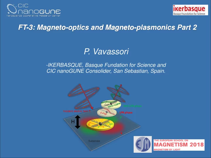
FT-3: Magneto-optics and Magneto-plasmonics Part 2
- P. Vavassori
- IKERBASQUE, Basque Fundation for Science and
CIC nanoGUNE Consolider, San Sebastian, Spain.
Incident electric field Ei
MO-LPR phase
y x
Ei
MO
H
LPR phase
Substrate
l’