
SLIDE 1
OPEN-MIDPLANE DIPOLES FOR A MUON COLLIDER*
- R. Weggel#, J. Kolonko & R. Scanlan, Particle Beam Lasers, Northridge, CA
- D. Cline & X. Ding, UCLA, Los Angeles, CA 90095, USA
- M. Anerella, R. Gupta, H. Kirk, B. Palmer & J. Schmalzle, BNL, Upton, NY
Abstract
For a muon collider with copious decay particles in the plane of the storage ring, open-midplane dipoles (OMD) may be preferable to tungsten-shielded cosine-theta dipoles of large aperture. The OMD should have its midplane completely free of material, so as to dodge the radiation from decaying muons. Analysis funded by a Phase I SBIR suggests that a field of 10-20 T should be feasible, with homogeneity of 1x10⁻⁴ and energy deposition low enough for conduction cooling to 4.2 K
- helium. If funded, a Phase II SBIR would refine the
analysis and build and test a proof-of-principle magnet.
CONCEPT, FIELD, FORCES & STRESSES Dipole Magnet with Truly Open Midplane
For muon colliders, cos(θ) dipoles are expensive because of the large bore needed to accommodate shielding to protect the conductor from radiation from the decaying muons. Open-midplane dipole (OMD) designs [1] banish windings from the path of this radiation. The design concept proposed here—an outgrowth of R&D for an LHC luminosity upgrade [2, 3]—banishes structure, too, from the midplane. The windings closest to the midplane are supported via magnetic attraction from
- utboard windings embedded in stainless steel [Fig. 1].
Figure 1: Cross section & field magnitude in 1st quadrant
- f an OMD. Half-gap = 15 mm; structural support: xmax=
40 cm; ymax= 20 cm. Muon beam is at [0, 0]. Lobed end of keyhole accommodates a radiation absorber of tungsten.
Fields & Forces: Equations & FEM Modeling
To generate designs with optimized combinations of central field B0, field homogeneity ∆B/B0, peak-field ratio Bmax/B0 and conductor volume or cost, while guaranteeing that the vertical magnetic force on each inboard coil will
*Supported by the U.S. DOE under Contract No. DE-
AC02-98CH10886 and SBIR contract DOE grant Nos. DE-FG02-07ER84855 & DE-FG02-08ER85037 —————————
#bob_weggel@mindspring.com
attract it away from the midplane, analytic equations are preferable to FEM methods to compute the fields and
- forces. For a bar of infinite length, rectangular X-section
and uniform current density J, the vertical field By is [4]: 1
, ,
ln
2 tan
- ,
where cB = μ0 J, and ui and vj are shorthand for ai−x; and bj−y, the horizontal and vertical distances, respectively, from a bar corner [ai, bj] to the field point [x, y]. is of the same form, with ui and vj interchanged. The vertical force Fy between two bars has sixteen terms of the form: 3 ln 23 tan
- tan
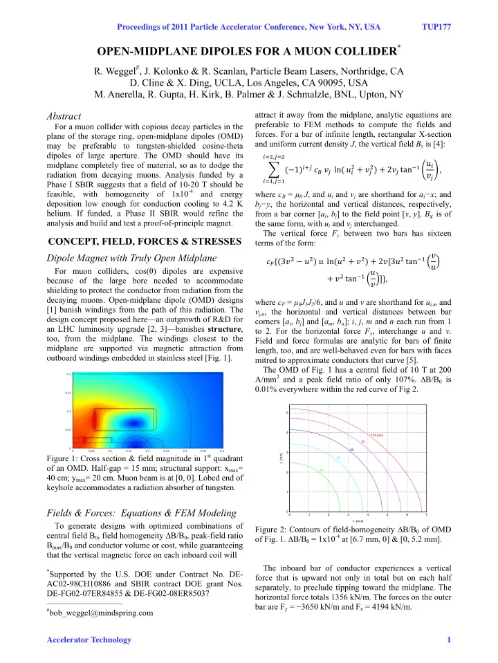
, where cF = μ0J1J2/6, and u and v are shorthand for ui,m and vj,n, the horizontal and vertical distances between bar corners [ai, bj] and [am, bn]; i, j, m and n each run from 1 to 2. For the horizontal force Fx, interchange u and v. Field and force formulas are analytic for bars of finite length, too, and are well-behaved even for bars with faces mitred to approximate conductors that curve [5]. The OMD of Fig. 1 has a central field of 10 T at 200 A/mm2 and a peak field ratio of only 107%. ∆B/B0 is 0.01% everywhere within the red curve of Fig 2. Figure 2: Contours of field-homogeneity ∆B/B0 of OMD
- f Fig. 1. ∆B/B0 = 1x10⁻⁴ at [6.7 mm, 0] & [0, 5.2 mm].
The inboard bar of conductor experiences a vertical force that is upward not only in total but on each half separately, to preclude tipping toward the midplane. The horizontal force totals 1356 kN/m. The forces on the outer bar are Fy = −3650 kN/m and Fx = 4194 kN/m.
1 2 3 4 5 1 2 3 4 5 6 7 100 ppm 80 60 40 20 x [mm] y [mm]