
SLIDE 1
On the nature of suboxide formation during reactive DC magnetron sputtering
- R. Schelfhout, K. Strijckmans, D. Depla
Dedicated Research on Advanced Films and Targets Ghent University
- R. Schelfhout
PSE 2018 www.DRAFT.ugent.be
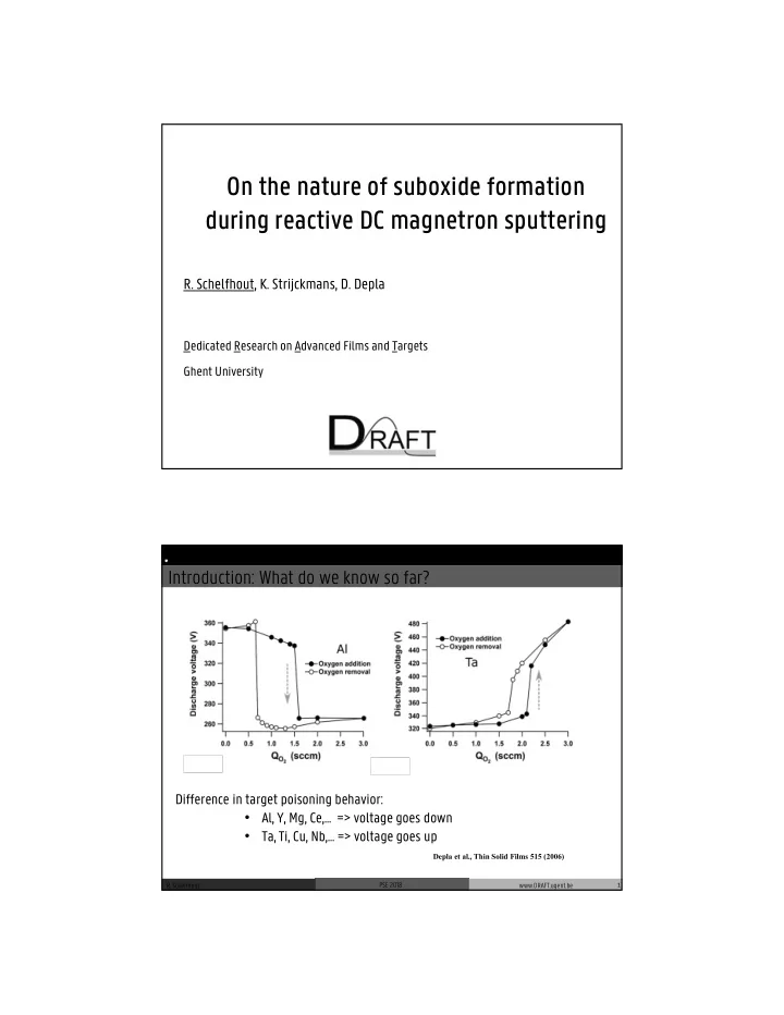
Introduction: What do we know so far?
Difference in target poisoning behavior:
- Al, Y, Mg, Ce,… => voltage goes down
- Ta, Ti, Cu, Nb,… => voltage goes up
Depla et al., Thin Solid Films 515 (2006)
1 Introduction In-vacuo XPS target analysis Ion Beam Oxidation Reactive magnetron sputtering Conclusion