Offshore Wind Farms Europe 2010 H. J. Koch, Senior Member, IEEE - - PDF document

offshore wind farms europe 2010
SMART_READER_LITE
LIVE PREVIEW

Offshore Wind Farms Europe 2010 H. J. Koch, Senior Member, IEEE - - PDF document

1 Offshore Wind Farms Europe 2010 H. J. Koch, Senior Member, IEEE Abstract --The offshore wind farms in Europe are under development and construction today. The first installations are in operation and many more are coming soon. At the beginning


slide-1
SLIDE 1

1

Offshore Wind Farms Europe 2010

  • H. J. Koch, Senior Member, IEEE

Abstract--The offshore wind farms in Europe are under development and construction today. The first installations are in

  • peration and many more are coming soon. At the beginning
  • ffshore wind farms were placed close to the coast line and

connected by AC sea cables to the on land network. Several hundred MW are typical wind farm sizes. Index Terms--Gas Insulated Switchgear (GIS), Offshore, Wind Farms, Substation Platform, Greater Gabbard, Galloper

  • I. INTRODUCTION

The voltages used are given by the sea cable and have values

  • f 132 kV to 220 kV when AC is used. Now the distances

from the coast line to the wind farms are increasing. With 50 to 60 km of length the application of AC sea cables comes to a limit, even when in one case 80 km are reached. The voltage levels of sea cables with XLPE solid insulation used today are 132 kV cables which allow 180 MVA per three phase system. For a 500 MVA wind park three 132 kV cables may be used. When distances are getting larger then DC converter stations with DC cables are used as in the case of Borwin 1 offshore wind farm where the total length (offshore and on land) is 130 km, too long for AC cables. In this contribution information is given on wind farms installed now in UK.

  • II. WIND FARMS IN EUROPE

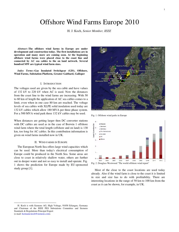
The European North Sea offers large wind capacities which can be used. More than today's electrical consumption of Europe could be produced in the North Sea. Some areas are close to coast in relatively shallow water, others are further

  • ut in deeper water and not so easy to install and operate. Fig.

1 shows the prediction for Europe made by EU-sponsored study group [1].

  • H. Koch is with Siemens AG, High Voltage, 91058 Erlangen, Germany

and Chairman of the IEEE PES Substations Committee and Siemens Standards & Regulations Principal Expert (e-mail: hermann.koch@siemens.com).

  • Fig. 1. Offshore wind parks in Europe
  • Fig. 2. Douglass Westwood "The world offshore wind report"

Most of the close to the coast locations are used today

  • already. Also if the wind farm is close to the coast it is limited

in size and size has to do with profitability. There are interesting locations in the range of 50 km to 100 km from the coast as it can be shown, for example, in UK.

slide-2
SLIDE 2

2

  • Fig. 3. Wind farm location of round 1, 2, and 3 in UK

In round 1 and 2 the locations found are typical 10-30 km away from the coast line and connected to the nearest network connecting point on land. In round 3 the locations are 50 - 220 km away from the coast line. The size of the wind farms is more than 1000 MVA up to 12 GW and cannot be connected to one network connection point [2].

  • III. GREATER GABBARD

The Greater Gabbard Offshore Winds Limited is a special purpose company. It was originally owned legally by Fluor International Limited and Airtricity Holdings Limited. Fluor sold its equity stake to Airtricity at financial close. Today the

  • wnership of the wind farm is 50 % by SSE who bought

Airtricity and 50 % by RWE-N Power [3]. The project is a 504 MW offshore wind farm located about 25 km offshore east of Suffolk in the UK, see Fig. 4.

  • Fig. 4. Grater Gabbard Location

The project site is at the Outer Thames Estuary with a site area of 147 km². The total electricity output per year will be 1.8 TWh which is generated by 140 Siemens wind turbines of 3.6 MW each. The wind turbines are connected inside the wind farm by 33 kV AC cables. To collect the total amount of 504 MW two offshore platforms are used the main one collecting 374.4MW from 104 wind turbines via 16 incoming cables of 33 kV AC as shown in Fig. 5.

  • Fig. 5. Inter wind farm power collecting array

The inter array cables are laid radially but the ends of the strings are looped using the smallest size of cable. The cable rating has to solve the typical hot spots:

  • A. Solar gain in j.tubes

This is where the cables come from the sea bed up to the platform through a j-shaped tube. Outside the water level the pipes which hold the cable will add heat to the system by solar radiation.

  • B. Buried in the sea bed

The heat dissipation when buried in the sea bed is depending on the depth of laying under the sea bed and thermal conductivity of the soil.

  • C. Land fall section in "dry" ground

When the cables come on land the heat dissipation in the soil is getting worse because of dryer ground and less thermal conductivity and the greater depth to cross the sea defences. In Fig. 7 the inter array 33 kV cables and the 150 kV export cable are shown from the Horns Rev offshore platform.

  • Fig. 7. Inter array 33 kV cables and 150 kV export cable
slide-3
SLIDE 3

3

The Greater Gabbard Main Platform has two decks and weighs about 2100 t, see Fig. 8.

  • Fig. 8. Greater Gabbard Main Platform

The main platform is connected by 16 incoming 33 kV cables which are laid radially to collect the energy from each wind turbine. A loop is created between two strings using the smallest size of cable to be able to provide conditioning supplies to the wind turbines in case of a cable fault. The cables are connected by 33 kV gas insulated switchgear (GIS) to the transformers. There are three transformers chosen to transform from 33 kV to 132 kV for the export cable to shore The 132 kV GIS switches the transformers and the 132 kV AC cable systems. The platform also contains a diesel generator for emergency supply and a refuge container for living in emergency cases when personnel gets stuck on the platform because of bad

  • weather. when there is no access to the platform by helicopter
  • r boat. Fire suppression systems, metering, LVDC batteries,

and potable water, anything what is needed in a substation are also provided. The situation today of the Greater Gabbard Offshore Substation is that the wind turbines are getting installed, the

  • ffshore platform is placed on the jacket 25 km offshore and

the export cables on land are being laid. Full operation will start in 2010. The offshore platforms are expensive to build; volume and weight are the strongest cost drivers. Therefore, offshore platforms need to be very compact. All components are

  • ptimized concerning their position and size on the platform.

In Fig. 9 a view to the 180MVA transformer 33 kV/132 kV is

  • shown. The transformer is bus duct connected to 33 kV and

cable connected to 132 kV switchgear. The compact design of the switchgear for 33 kV and 132 kV is shown in Fig. 10.

  • Fig. 9. 33 kV/132 kV transformer, 180 MVA
  • Fig. 10. 33 kV/132 kV switchgear
slide-4
SLIDE 4

4

  • IV. GALLOPER PLATFORM

The next offshore substation on the schedule is the Galloper Platform which is now under construction in the harbor of South Shields in England. The platform sail out in May to be placed on the jacket foundation. The export cable

  • f 132 kV will then be connected to the Greater Gabbard
  • Platform. The Galloper Platform has two 90 MVA 33 kV/132

kV transformers and connects the remaining 129.6MW of wind power. In Fig. 11 a photo shows the status of the platform in January 2010.

  • Fig. 11. Galloper Platform

The lower deck holds the low voltage supply, rescue container, potable water tanks, protection and SCADA rooms. The upper deck accommodates the 33 kV/132 kV transformers in the center, the 132 kV compensation coils located outdoor without a roof, whereas the 33 kV GIS and 132kV GIS are located indoors.

  • V. CONCLUSION

Large scale offshore wind farms are built in the North Sea in Europe today and many will follow. According to European Authorities more than 100 GW are in planning. UK and Germany have plans for more than 20 GW each. The European countries along the North Sea have found the PENTA coordination group on ministerial level. Members are United Kingdom, the Netherlands, Germany, Denmark, Sweden, and Norway. Offshore substations require high reliability, under extreme environmental conditions and are not easily accessible when 50 km offshore. Substations on land are today in most cases a project related solution. Each substation is different, mainly

  • n the control and monitoring level. Software is something

which changes relatively quick in substations. New releases are installed with the next visit of the substation. Offshore substations will not accept such operation and maintenance activities because a visit is expensive. One rule says: Offshore is 10 times more expensive than on land. This will in consequence be the driver for new substation

  • design. No maintenance on primary equipment, e. g. trans-

former oil, insulating gas. The control and protection devices can simply be replaced by self-installing software components and no need of experts to be sent offshore. Multi-skilled personnel to be sent out to the platform are able to take care about any type of maintenance: primary equipment, protection, control, monitoring, and supply systems. The use of offshore substations may be the innovation source for simplification of substation solutions.

  • VI. REFERENCES

[1] University of Oldenburg, University of Hannover, ILF, Siemens, Durchführbarkeitsstudie über einen auf der GIL-Technik basierenden Nordseeverbund europäischer Offshore-Windkraftanlagen für den Stromhandel, 30.09.2009 [2] National Grid, UK, Transmission Networks, Offshore Development, Information Statement, December 2009 [3] National Grid, UK, The Crown Estate, Round 3, Offshore Wind Farm Connection Study, Version 1.0, 12.12.2008

  • VII. BIOGRAPHIES

Dr.-Ing. Hermann Koch was born in November 1954 in Hauswurz, Germany. In 1979 he graduated in Industrial Control Engineering at the Fachhoch- schule Rüsselsheim. From 1980-1981 he studied at New Jersey Institute

  • f Technology, Newark, New Jersey, USA. 1986 he

graduated in Electrical Engineering at the Technical University of Darmstadt. He received his Dr.-Ing. degree in 1990 from the Technical University of

  • Darmstadt. Since 1991 he is working with Siemens

High Voltage Division in different responsibilities including Gas Insulated Switchgear and Transmission Lines. Currently he is Director of Standards and Regulations of the High Voltage Technology. Hermann Koch is Chairman of the IEEE PES Substations Committee. In IEC he is Secretary of SC 17C High Voltage Switchgear Assemblies. In CIGRE he is member of the Strategic Advisory Group of SC B3 Substations. He has published more than 130 technical papers at International Confer- ences and magazines and holds 31 patents in the field of gas insulated technology which is his area of expertise. He is engaged in studies, innova- tions, and R&D activities for high voltage gas insulated power transmission systems.