
SLIDE 1
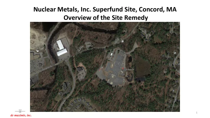
Nuclear Metals, Inc. Superfund Site, Concord, MA Overview of the Site Remedy
1
Nuclear Metals, Inc. Superfund Site, Concord, MA Overview of the - - PowerPoint PPT Presentation
Nuclear Metals, Inc. Superfund Site, Concord, MA Overview of the Site Remedy 1 Outline Site Background / Regulatory History Remedy Framework RD/RA Process and Schedule Post-Remedy Considerations, Effect of Institutional Controls
1
2
3
Cooling Water Pond
Sphagnum Bog Old Landfill Area
Towards Assabet River ~500 feet NW
4
5
6
7
EPA Chris Smith Remedial Project Manager MassDEP Garry Waldeck Project Manager de maximis, inc. - General Contractor Bruce Thompson - Project Coordinator Jessie McCusker - Site-Wide Soils and Sediments and Holding Basin Containment Amy Hoffman – ISS and Sitewide Monitoring Nathan Hunt – HCTS O&M and1,4-D in Bedrock Geosyntec Consultants Carl Elder, Ph.D., P.E. – Overall PM ISS and 1,4-D in Bedrock Dave Adilman, P.G. – Task Manager Haley & Aldrich, Inc. Mark Kelley, P.E. – Overall PM Site-Wide Soils and Sediments Mark Kelley, P.E. – Task Manager Holding Basin Containment Tim Crowl, P.E. – Task Manager ddms, inc. Heidi Gaedy Database Website, GIS, Project Portal Polly Newbold Data Validation O&M, Inc. Nicolas Carabillo HCTS O&M PM AECOM Andy Schukta EPA Oversight Contractor Community Groups Town of Concord Reuse Cmte 2229 Main St Cmte CREW Green Acton Laboratories Alpha Analytical GEL Drilling TBD DDES, Inc. Matt Norton, CIH, CSP Radiation Safety Officer
8
9
* This is a best case schedule projection.
10
11
12
13
14
15
16
*Note – this is starting point, final scope dependent on PDI and confirmatory sampling during RA.
17
18
19
Extent of Overburden or Bedrock Groundwater Exceeding Safe Drinking Water Level
20
21
22
23
24
25
26
Estimated Capture Zone for EW-1 at 19.6 gpm
27
28
29