MOBILE COMPUTING CSE 40814/60814 Fall 2015 Dynamic Host - - PDF document

mobile computing
SMART_READER_LITE
LIVE PREVIEW

MOBILE COMPUTING CSE 40814/60814 Fall 2015 Dynamic Host - - PDF document

11/15/15 MOBILE COMPUTING CSE 40814/60814 Fall 2015 Dynamic Host Configuration Protocol Application simplification of installation and maintenance of networked computers supplies systems with all necessary information, such as IP


slide-1
SLIDE 1

11/15/15 1

MOBILE COMPUTING

CSE 40814/60814 Fall 2015

Dynamic Host Configuration Protocol

  • Application
  • simplification of installation and maintenance of networked computers
  • supplies systems with all necessary information, such as IP address, DNS

server address, domain name, subnet mask, default router etc.

  • enables automatic integration of systems into an Intranet or the Internet,

can be used to acquire a COA for Mobile IP
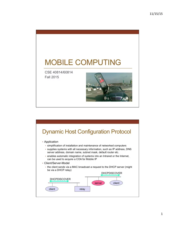
  • Client/Server-Model
  • the client sends via a MAC broadcast a request to the DHCP server (might

be via a DHCP relay) client relay client server DHCPDISCOVER DHCPDISCOVER

slide-2
SLIDE 2

11/15/15 2

DHCP – Protocol Mechanisms

t i m e server (not selected) client server (selected) initialization collection of replies selection of configuration initialization completed release confirmation of configuration delete context determine the configuration DHCPDISCOVER DHCPOFFER DHCPREQUEST (reject) DHCPACK DHCPRELEASE DHCPDISCOVER DHCPOFFER DHCPREQUEST (options) determine the configuration

DHCP Characteristics

  • Server
  • several servers can be configured for DHCP, coordination not yet

standardized (i.e., manual configuration)

  • Renewal of configurations
  • IP addresses have to be requested periodically, simplified protocol
  • Options
  • available for routers, subnet mask, NTP (network time protocol)

timeserver, SLP (service location protocol) directory, DNS (domain name system)

  • Big security problems!
  • no authentication of DHCP information specified
slide-3
SLIDE 3

11/15/15 3

Mobility

Home network: permanent “home” of mobile

(e.g., 128.119.40/24)

Permanent address: address in home network, can always be used to reach mobile

e.g., 128.119.40.186

Home agent: entity that will perform mobility functions on behalf of mobile, when mobile is remote

wide area network

correspondent

Mobility

Care-of-address: address in visited network.

(e.g., 79.129.13.2) wide area network

Visited network: network in which mobile currently resides (e.g., 79.129.13/24) Permanent address: remains constant (e.g., 128.119.40.186) Correspondent: wants to communicate with mobile

slide-4
SLIDE 4

11/15/15 4

Finding Somebody

  • Let routing handle it:
  • routers advertise permanent address of mobile-nodes-

in-residence via usual routing table exchange

  • routing tables indicate where each mobile located
  • no changes to end-systems
  • NOT SCALABLE!
  • Let end-systems handle it:
  • indirect routing: communication from correspondent to

mobile goes through home agent, then forwarded to remote

  • direct routing: correspondent gets foreign address of

mobile, sends directly to mobile

Mobility: Registration

End result:

  • Foreign agent knows about mobile
  • Home agent knows location of mobile

wide area network

home network visited network

1

mobile contacts foreign agent on entering visited network

2

foreign agent contacts home agent: “this mobile is resident in my network”

slide-5
SLIDE 5

11/15/15 5

Mobility via Indirect Routing

wide area network

home network visited network

3 2 4 1 correspondent addresses packets using home address of mobile home agent intercepts packets, forwards to foreign agent foreign agent receives packets, forwards to mobile mobile replies directly to correspondent

Indirect Routing: Comments

  • Mobile uses two addresses:
  • permanent address: used by correspondent (hence mobile

location is transparent to correspondent)

  • care-of-address: used by home agent to forward datagrams to

mobile

  • foreign agent functions may be done by mobile itself
  • triangle routing: correspondent-home-network-mobile
  • inefficient when

correspondent, mobile are in same network

slide-6
SLIDE 6

11/15/15 6

Indirect Routing: Moving Between Networks

  • Suppose mobile user moves to another network
  • registers with new foreign agent
  • new foreign agent registers with home agent
  • home agent updates care-of-address for mobile
  • packets continue to be forwarded to mobile (but with new care-of-

address)

  • Mobility, changing foreign networks transparent: ongoing

connections can be maintained!

Mobility via Direct Routing

wide area network

home network visited network

4 2 4 1 correspondent requests, receives foreign address of mobile correspondent forwards to foreign agent foreign agent receives packets, forwards to mobile mobile replies directly to correspondent 3

slide-7
SLIDE 7

11/15/15 7

Mobility via Direct Routing: Comments

  • Overcome triangle routing problem
  • Non-transparent to correspondent: correspondent must

get care-of-address from home agent

  • what if mobile changes visited network?

wide area network

1

foreign net visited at session start anchor foreign agent

2 4

new foreign agent

3 5

correspondent agent correspondent new foreign network

Accommodating Mobility with Direct Routing

  • Anchor foreign agent: “anchor FA” in first visited network
  • Data always routed first to anchor FA
  • When mobile moves: new FA arranges to have data

forwarded from old FA (chaining)

slide-8
SLIDE 8

11/15/15 8

Mobile IP

  • RFC 3220
  • Has many features we’ve seen:
  • home agents, foreign agents, foreign-agent registration, care-of-

addresses, encapsulation (packet-within-a-packet)

  • Three components to standard:
  • indirect routing of datagrams
  • agent discovery
  • registration with home agent

Mobile IP: Indirect Routing

Permanent address: 128.119.40.186 Care-of address: 79.129.13.2 dest: 128.119.40.186

packet sent by correspondent

dest: 79.129.13.2 dest: 128.119.40.186

packet sent by home agent to foreign agent: a packet within a packet

dest: 128.119.40.186

foreign-agent-to-mobile packet

slide-9
SLIDE 9

11/15/15 9

Mobile IP: Agent Discovery

  • Agent advertisement: foreign/home agents advertise

service by broadcasting ICMP messages (typefield = 9)

RBHFMGV bits reserved type = 16 type = 9 code = 0 = 9 checksum = 9 router address standard ICMP fields mobility agent advertisement extension length sequence # registration lifetime

0 or more care-of- addresses

8 16 24

R bit: registration required H,F bits: home and/or foreign agent

Mobile IP: Registration Example

visited network: 79.129.13/24 home agent HA: 128.119.40.7 foreign agent COA: 79.129.13.2

COA: 79.129.13.2

….

ICMP agent adv.

Mobile agent MA: 128.119.40.186

registration req.

COA: 79.129.13.2 HA: 128.119.40.7 MA: 128.119.40.186 Lifetime: 9999 identification:714 ….

registration req.

COA: 79.129.13.2 HA: 128.119.40.7 MA: 128.119.40.186 Lifetime: 9999 identification: 714 encapsulation format ….

registration reply

HA: 128.119.40.7 MA: 128.119.40.186 Lifetime: 4999 Identification: 714 encapsulation format ….

registration reply

HA: 128.119.40.7 MA: 128.119.40.186 Lifetime: 4999 Identification: 714 ….

time

slide-10
SLIDE 10

11/15/15 10

Cell Network

Mobile Switching Center

Public telephone network, and Internet

Mobile Switching Center

q connects cells to wide area net q manages call setup q handles mobility

MSC

q covers geographical

region

q base station (BS)

analogous to 802.11 AP

q mobile users attach

to network through BS

q air-interface: physical

and link layer protocol between mobile and BS

cell wired network

Mobility Management

  • Challenge: roaming message destination
  • Location management
  • Roaming management
  • Handoff management
slide-11
SLIDE 11

11/15/15 11

Example: Cellular Networks Mobility in Cellular Networks

  • Home network: network of cellular provider you subscribe

to (e.g., Sprint PCS, Verizon)

  • home location register (HLR): database in home network

containing permanent cell phone #, profile information (services, preferences, billing), information about current location (could be in another network)

  • Visited network: network in which mobile currently resides
  • visitor location register (VLR): database with entry for each user

currently in network

  • could be home network
slide-12
SLIDE 12

11/15/15 12

GSM: Indirect Routing

Public switched telephone network mobile user home Mobile Switching Center

HLR

home network visited network correspondent Mobile Switching Center

VLR

1 call routed to home network 2

home MSC consults HLR, gets roaming number of mobile in visited network

3 home MSC sets up 2nd leg of call to MSC in visited network 4 MSC in visited network completes call through base station to mobile

GSM: Handoff with Common MSC

  • Handoff goal: route call via new

base station (without interruption)

  • Reasons for handoff:
  • stronger signal to/from new BSS

(continuing connectivity, less battery drain)

  • load balance: free up channel in

current BSS

  • GSM doesn’t mandate why to

perform handoff (policy), only how (mechanism)

  • Handoff initiated by old BSS

Mobile Switching Center

VLR

  • ld BSS

new BSS

  • ld

routing new routing

slide-13
SLIDE 13

11/15/15 13

GSM: Handoff with Common MSC

  • 1. old BSS informs MSC of impending

handoff, provides list of 1+ new BSSs

  • 2. MSC sets up path (allocates resources)

to new BSS

  • 3. new BSS allocates radio channel for

use by mobile

  • 4. new BSS signals MSC, old BSS: ready
  • 5. old BSS tells mobile: perform handoff to

new BSS

  • 6. mobile, new BSS signal to activate new

channel

  • 7. mobile signals via new BSS to MSC:

handoff complete. MSC reroutes call 8 MSC-old-BSS resources released

Mobile Switching Center

VLR

  • ld BSS

1 3 2 4 5 6 7 8

new BSS

GSM: Handoff Between MSCs

  • Anchor MSC: first MSC

visited during call

  • call remains routed through

anchor MSC

  • new MSCs add on to end of

MSC chain as mobile moves to new MSC

  • IS-41 allows optional path

minimization step to shorten multi-MSC chain

home network Home MSC PSTN correspondent MSC anchor MSC MSC MSC

(a) before handoff

slide-14
SLIDE 14

11/15/15 14

GSM: Handoff Between MSCs

  • Anchor MSC: first MSC

visited during call

  • call remains routed through

anchor MSC

  • new MSCs add on to end of

MSC chain as mobile moves to new MSC

  • IS-41 allows optional path

minimization step to shorten multi-MSC chain

home network Home MSC PSTN correspondent MSC anchor MSC MSC MSC

(b) after handoff

Impact on Higher Layer Protocols

  • logically, impact should be minimal …
  • best effort service model remains unchanged
  • TCP and UDP can (and do) run over wireless, mobile
  • … but performance-wise:
  • packet loss/delay due to bit-errors (discarded packets, delays for

link-layer retransmissions), and handoff

  • TCP interprets loss as congestion, will decrease congestion window

unnecessarily

  • delay impairments for real-time traffic
  • limited bandwidth of wireless links
slide-15
SLIDE 15

11/15/15 15

UDP – User Datagram Protocol

  • Unreliable and unordered datagram service
  • Adds multiplexing
  • No flow control
  • Endpoints identified by ports
  • servers have well-known ports
  • see /etc/services on Unix
  • Header format
  • Optional checksum

SrcPort DstPort Checksum Length Data 16 31

TCP – Transmission Control Protocol

  • Connection-oriented
  • Byte-stream

– app writes bytes – TCP sends segments – app reads bytes

  • Full duplex
  • Flow control: keep sender from
  • verrunning receiver
  • Congestion control: keep sender

from overrunning network

Application process Write bytes TCP Send buffer Segment Segment Segment Transmit segments Application process Read bytes TCP Receive buffer

■ ■ ■

slide-16
SLIDE 16

11/15/15 16

TCP

Options (variable) Data Checksum SrcPort DstPort HdrLen Flags UrgPtr AdvertisedWindow SequenceNum Acknowledgment 4 10 16 31

TCP’s 3-way handshake

Active participant (client) Passive participant (server) SYN, SequenceNum = x A C K , A c k n

  • w

l e d g m e n t = y + 1 A c k n

  • w

l e d g m e n t = x + 1 S Y N + A C K , S e q u e n c e N u m = y ,

slide-17
SLIDE 17

11/15/15 17

Connection Termination

First participant Second participant FIN, SequenceNum = x A C K , A c k n

  • w

l e d g m e n t = y + 1 A C K , A c k n

  • w

l e d g m e n t = x + 1 , F I N , S e q u e n c e N u m = y , A c k n

  • w

l e d g m e n t = x + 1

Motivation

  • Transport protocols typically designed for
  • fixed end-systems
  • fixed, wired networks
  • Research activities
  • performance
  • congestion control
  • efficient retransmissions
  • TCP congestion control
  • packet loss in fixed networks typically due to (temporary) overload

situations

  • router have to discard packets as soon as the buffers are full
  • TCP recognizes congestion only indirect via missing acknowledgements,

retransmissions at full sending rate unwise, they would only contribute to the congestion and make it even worse

  • slow-start algorithm as reaction
slide-18
SLIDE 18

11/15/15 18

Packet Loss

Arriving packet Next free buffer Free buffers Queued packets Next to transmit (a) Arriving packet Next to transmit (b) Drop Destination 1.5-Mbps T1 link Router Source 2 Source 1 100-Mbps FDDI 10-Mbps Ethernet

TCP Congestion Control

  • Idea
  • assumes best-effort network (FIFO or FQ routers) each source

determines network capacity for itself

  • uses implicit feedback
  • ACKs pace transmission (self-clocking)
  • Challenge
  • determining the available capacity in the first place
  • adjusting to changes in the available capacity
slide-19
SLIDE 19

11/15/15 19

AIMD

  • Objective: adjust to changes in the available capacity
  • New state variable per connection: CongestionWindow
  • limits how much data source has in transit

MaxWin = MIN(CongestionWindow, AdvertisedWindow) EffWin = MaxWin - (LastByteSent – LastByteAcked)

  • Idea:
  • increase CongestionWindow when congestion goes down
  • decrease CongestionWindow when congestion goes up
  • Question: how does the source determine whether or not

the network is congested?

  • Answer: a timeout occurs
  • timeout signals that a packet was lost
  • packets are seldom lost due to transmission error
  • lost packet implies congestion

AIMD

  • Algorithm

– increment CongestionWindow by one packet per RTT (linear

increase)

– divide CongestionWindow by two whenever a timeout occurs

(multiplicative decrease)

Source Destination

slide-20
SLIDE 20

11/15/15 20

AIMD

  • Sawtooth behavior

60 20 1.0 2.0 3.0 4.0 5.0 6.0 7.0 8.0 9.0 Time (seconds) 70 30 40 50 10 10.0

Slow Start

  • Objective: determine the available capacity in the

beginning

  • Idea:
  • begin with CongestionWindow = 1 packet
  • double CongestionWindow each RTT

(increment by 1 packet for each ACK)

Source Destination

slide-21
SLIDE 21

11/15/15 21

Slow Start

  • Exponential growth, but slower than all at once
  • Used…
  • when first starting connection
  • when connection goes dead waiting for timeout
  • Trace
  • Problem: lose up to half a CongestionWindow’s worth of

data

60 20 1.0 2.0 3.0 4.0 5.0 6.0 7.0 8.0 9.0 Time (seconds) 70 30 40 50 10

Fast Retransmit/Fast Recovery

  • TCP sends an acknowledgement only

after receiving a packet

  • If a sender receives several

acknowledgements for the same packet, this is due to a gap in received packets at the receiver

  • However, the receiver got all packets up

to the gap and is actually receiving packets

  • Therefore, packet loss is not due to

congestion, continue with current congestion window (do not use slow- start)

Packet 1 Packet 2 Packet 3 Packet 4 Packet 5 Packet 6 Retransmit packet 3 ACK 1 ACK 2 ACK 2 ACK 2 ACK 6 ACK 2 Sender Receiver

slide-22
SLIDE 22

11/15/15 22

Fast Retransmit/Fast Recovery

  • Fast recovery
  • skip the slow start phase
  • go directly to half the last successful CongestionWindow

(ssthresh)

60 20 1.0 2.0 3.0 4.0 5.0 6.0 7.0 Time (seconds) 70 30 40 50 10

Mobility Affecting TCP-Mechanisms

  • TCP assumes congestion if packets are dropped
  • typically wrong in wireless networks, here we often have packet

loss due to transmission errors

  • furthermore, mobility itself can cause packet loss, if e.g. a mobile

node roams from one access point (e.g., foreign agent in Mobile IP) to another while there are still packets in transit to the wrong access point and forwarding is not possible

  • The performance of an unchanged TCP degrades

severely

  • however, TCP cannot be changed fundamentally due to the large

base of installation in the fixed network, TCP for mobility has to remain compatible

  • the basic TCP mechanisms keep the whole Internet together
slide-23
SLIDE 23

11/15/15 23

Early Approach: Indirect TCP

  • Indirect TCP or I-TCP segments the connection
  • no changes to the TCP protocol for hosts connected to the wired Internet,

millions of computers use (variants of) this protocol

  • optimized TCP protocol for mobile hosts
  • splitting of the TCP connection at, e.g., the foreign agent into 2 TCP

connections, no real end-to-end connection any longer

  • hosts in the fixed part of the net do not notice the characteristics of the

wireless part

mobile host access point (foreign agent)

“wired“ Internet “wireless“ TCP standard TCP

I-TCP Socket and State Migration

mobile host

access point2 Internet

access point1

socket migration and state transfer

slide-24
SLIDE 24

11/15/15 24

Indirect TCP

  • Advantages
  • no changes in the fixed network necessary, no changes for the hosts

(TCP protocol) necessary, all current optimizations to TCP still work

  • transmission errors on the wireless link do not propagate into the fixed

network

  • simple to control, mobile TCP is used only for one hop between, e.g., a

foreign agent and mobile host

  • therefore, a very fast retransmission of packets is possible, the short

delay on the mobile hop is known

  • Disadvantages
  • loss of end-to-end semantics, an acknowledgement to a sender does

now not any longer mean that a receiver really got a packet, foreign agents might crash

  • higher latency possible due to buffering of data within the foreign agent

and forwarding to a new foreign agent

Snooping TCP

  • “Transparent“ extension of TCP within the foreign agent
  • buffering of packets sent to the mobile host
  • lost packets on the wireless link (both directions!) will be retransmitted

immediately by the mobile host or foreign agent, respectively (so called “local” retransmission)

  • the foreign agent therefore “snoops” the packet flow and recognizes

acknowledgements in both directions, it also filters ACKs

  • changes of TCP only within the foreign agent

“wired“ Internet buffering of data end-to-end TCP connection local retransmission correspondent host foreign agent mobile host

snooping of ACKs

slide-25
SLIDE 25

11/15/15 25

Snooping TCP

  • Data transfer to the mobile host
  • FA buffers data until it receives ACK of the MH, FA detects packet loss via

duplicated ACKs or time-out

  • fast retransmission possible, transparent for the fixed network
  • Data transfer from the mobile host
  • FA detects packet loss on the wireless link via sequence numbers, FA answers

directly with a NACK to the MH

  • MH can now retransmit data with only a very short delay
  • Advantages
  • end-to-end semantics preserves, no changes to correspondent host (and few

to mobile host)

  • no state handover (time-out and retransmission)
  • handover: next FA may not use this approach
  • Problems
  • snooping TCP does not isolate the wireless link as good as I-TCP
  • snooping might be useless depending on encryption schemes

Mobile TCP

  • Special handling of lengthy and/or frequent disconnections
  • M-TCP splits as I-TCP does
  • unmodified TCP fixed network to supervisory host (SH)
  • optimized TCP SH to MH
  • Supervisory host
  • no caching, no retransmission
  • monitors all packets, if disconnection detected
  • set sender window size to 0
  • sender automatically goes into persistent mode
  • old or new SH reopen the window
  • Advantages
  • maintains semantics, supports disconnection, no buffer forwarding, no changes

to sender’s TCP

  • Disadvantages
  • loss on wireless link propagated into fixed network
  • adapted TCP on wireless link
slide-26
SLIDE 26

11/15/15 26

Fast Retransmit/Fast Recovery

  • Change of foreign agent often results in packet loss
  • TCP reacts with slow-start although there is no congestion
  • Forced fast retransmit
  • as soon as the mobile host has registered with a new foreign agent, the

MH sends duplicated acknowledgements on purpose

  • this forces the fast retransmit mode at the communication partners
  • additionally, the TCP on the MH is forced to continue sending with the

actual window size and not to go into slow-start after registration

  • Advantage
  • simple changes result in significant higher performance
  • Disadvantage
  • focus on handover losses (not wireless link errors)

Transmission/Time-out Freezing

  • Mobile hosts can be disconnected for a longer time
  • no packet exchange possible, e.g., in a tunnel, disconnection due to
  • verloaded cells with higher priority traffic
  • TCP disconnects after time-out completely
  • TCP freezing
  • MAC layer is often able to detect interruption in advance
  • MAC can inform TCP layer of upcoming loss of connection
  • TCP stops sending, but does not assume a congested link
  • MAC layer signals again if reconnected
  • Advantage
  • scheme is independent of data
  • Disadvantage
  • TCP on mobile host has to be changed, mechanism depends on MAC

layer

slide-27
SLIDE 27

11/15/15 27

Selective Retransmission

  • TCP acknowledgements are often cumulative
  • ACK n acknowledges correct and in-sequence receipt of packets up to n
  • if single packets are missing quite often a whole packet sequence

beginning at the gap has to be retransmitted (go-back-n), thus wasting bandwidth

  • Selective retransmission as one solution
  • RFC2018 allows for acknowledgements of single packets, not only

acknowledgements of in-sequence packet streams without gaps

  • sender can now retransmit only the missing packets
  • Advantage
  • much higher efficiency
  • Disadvantage
  • more complex software in a receiver, more buffer needed at the receiver

Transaction Oriented TCP (T/TCP)

  • TCP phases
  • connection setup, data transmission, connection release
  • using 3-way-handshake needs 3 packets for setup and release,

respectively

  • thus, even short messages need a minimum of 7 packets!
  • Transaction oriented TCP
  • RFC1644, T/TCP, describes a TCP version to avoid this overhead
  • connection setup, data transfer and connection release can be combined
  • thus, only 2 or 3 packets are needed
  • Advantage
  • efficiency
  • Disadvantage
  • requires changed TCP
  • mobility not longer transparent
slide-28
SLIDE 28

11/15/15 28

Comparison of Different Approaches for a “Mobile” TCP

Approach Mechanism Advantages Disadvantages Indirect TCP splits TCP connection into two connections isolation of wireless link, simple loss of TCP semantics, higher latency at handover Snooping TCP “snoops” data and acknowledgements, local retransmission transparent for end-to- end connection, MAC integration possible problematic with encryption, bad isolation

  • f wireless link

M-TCP splits TCP connection, chokes sender via window size Maintains end-to-end semantics, handles long term and frequent disconnections Bad isolation of wireless link, processing

  • verhead due to

bandwidth management Fast retransmit/ fast recovery avoids slow-start after roaming simple and efficient mixed layers, not transparent Transmission/ time-out freezing freezes TCP state at disconnect, resumes after reconnection independent of content

  • r encryption, works for

longer interrupts changes in TCP required, MAC dependant Selective retransmission retransmit only lost data very efficient slightly more complex receiver software, more buffer needed Transaction

  • riented TCP

combine connection setup/release and data transmission Efficient for certain applications changes in TCP required, not transparent